5.4.3.5 Installing/connecting a field bus module
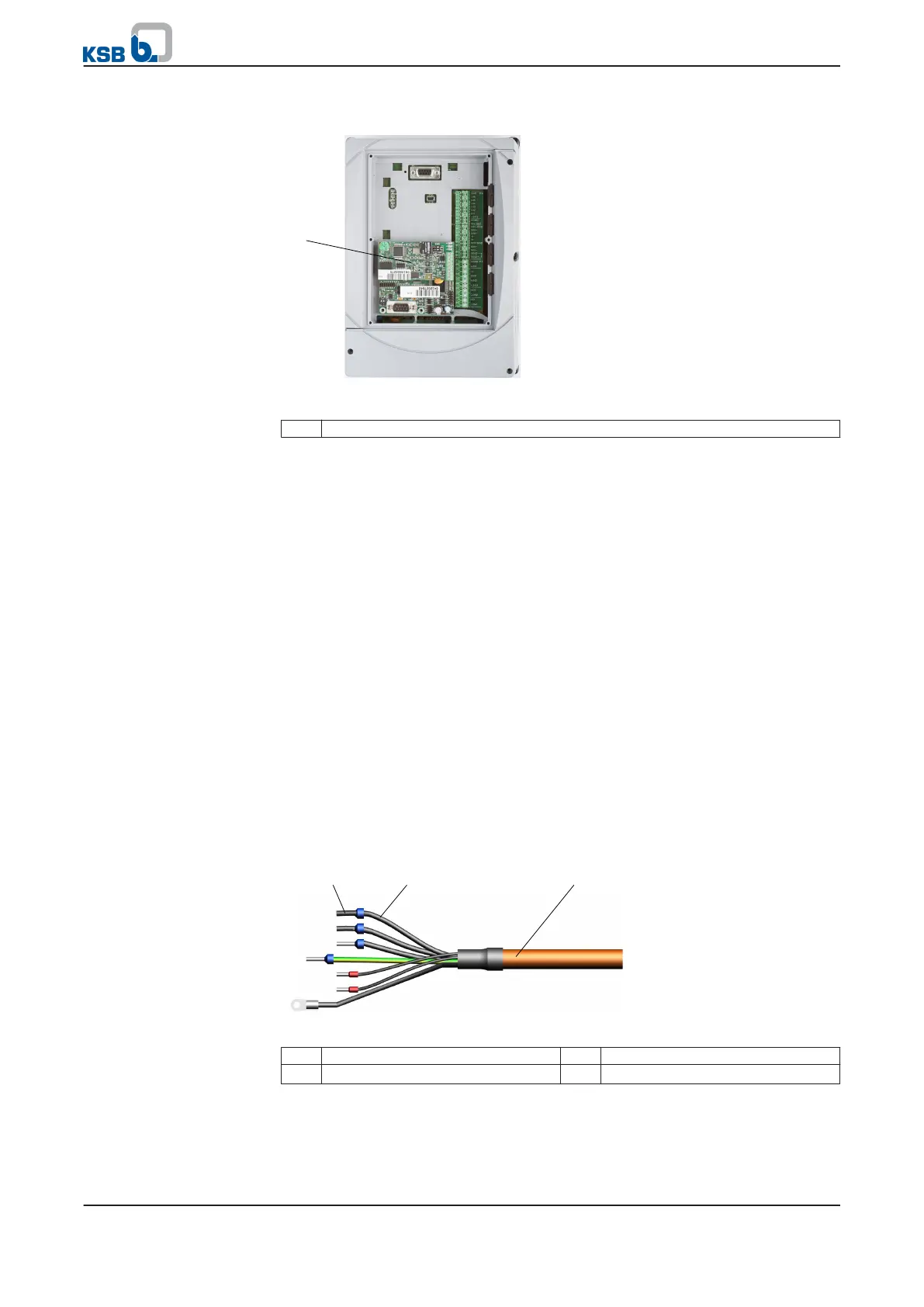
Fig. 15: Installing a field bus module in PumpDrive
1 Field bus module
Observe the following when installing the field bus module:
▪ Only connect or remove the field bus module when it is de-energised.
▪ Always attach the field bus module to the lower P8 slot on the PumpDrive.
(⇨ Section 5.4.3.6 Page 31)
▪ The procedure for installing the field bus modules is identical for all types (LON,
Profibus, Modbus).
▪ Observe the product literature provided with the field bus module when
installing the device.
Observe the following when connecting the field bus module:
▪ To ensure radio frequency shielding, use shielded cables for LON and Profibus
and install these in accordance with EMC requirements.
▪ Use cable type 0.5 mm AWG 24 (e.g. G-Y(st) Y 2 x 2 x 0.8 mm
2
) at minimum.
▪ A minimum distance of 0.3 metres is recommended between such cables and
other electric conductors.
▪ Do not use the bus cable to make any further connections in addition to the field
bus module (for example, 230 V alert and 24 V start).
▪ Observe the product literature provided with the field bus module when
connecting the device.
5.4.3.6 Connecting the control cable
Fig. 16: Structure of electric cable
1 Wire end sleeve 2 Core
3 Cable
Installing the field bus
module
Connecting the field bus
module
5 Installation at Site
PumpDrive
31 of 162