PumpDrive
∆ ∆p ∆n ∆
∆
U[V,f]
p setpoint
Controlled system
p
Speed controller
actual
p
Process controller
(PI controller)
actual
(PI controller)
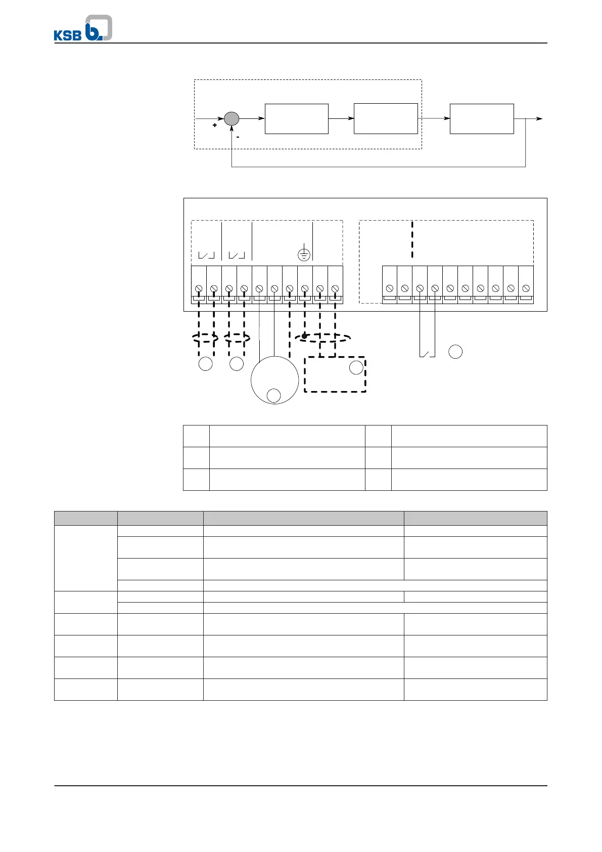
Fig. 28: Closed-loop control mode block diagram
G
ND
DI6
DI5
D
I4
D
I3
DI2
D
I1
+
24V
A
GN
D
AN
-
O
U
T
20191817161514131211
1
AGND
AIN1
GND
AIN2
+24V
NO2
COM2
NO1
COM1
10931 2 4 5 6 7 8
Sensor
4...20mA
P4
P7
5
2
0V
S ignal
3 4
Fig. 29: Terminal wiring diagram, closed-loop control mode (dashed line = optional)
1 Start/stop 2 External setpoint signal
(⇨ Section 7.1.1.2 Page 49)
3 Signal relay 1
(⇨ Section 7.4.2 Page 95)
4 Signal relay 2
(⇨ Section 7.4.2 Page 95)
5 External sensor signal
(⇨ Section 7.1.1.4 Page 54)
Table 54: Closed-loop control mode
Function Input/connection Specification Setting range/parameter value
Setpoint
specification
P7 terminal strip Analog input 1 (P7: 9/10) 5-10 V DC ≙ 25-50 Hz
Graphical control
panel
Configurable setpoint
(3-5-2-1)
50 - 100 % ≙ 25 - 50 Hz
Standard control
panel
(⇨ Section 6.1.5 Page 39) 50 - 100 % ≙ 25 - 50 Hz
Field bus See field bus module literature
Start
command
P4 terminal strip Digital input 1 (P4: 13/14) Start in automatic mode
Field bus See field bus module literature
Process
controller
Graphical control
panel
PI Auto (3-9-1-6) Deactivated
Process
controller
Graphical control
panel
PI mode (3-9-1-1) Disabled
Operating
mode
Graphical control
panel
MAN-OFF-AUTO AUTO
Process
controller
Graphical control
panel
PI mode (3-9-1-1) Enabled
Circuit diagram (⇨ Section 9 Page 99)
7 Commissioning/shutdown
PumpDrive
55 of 162