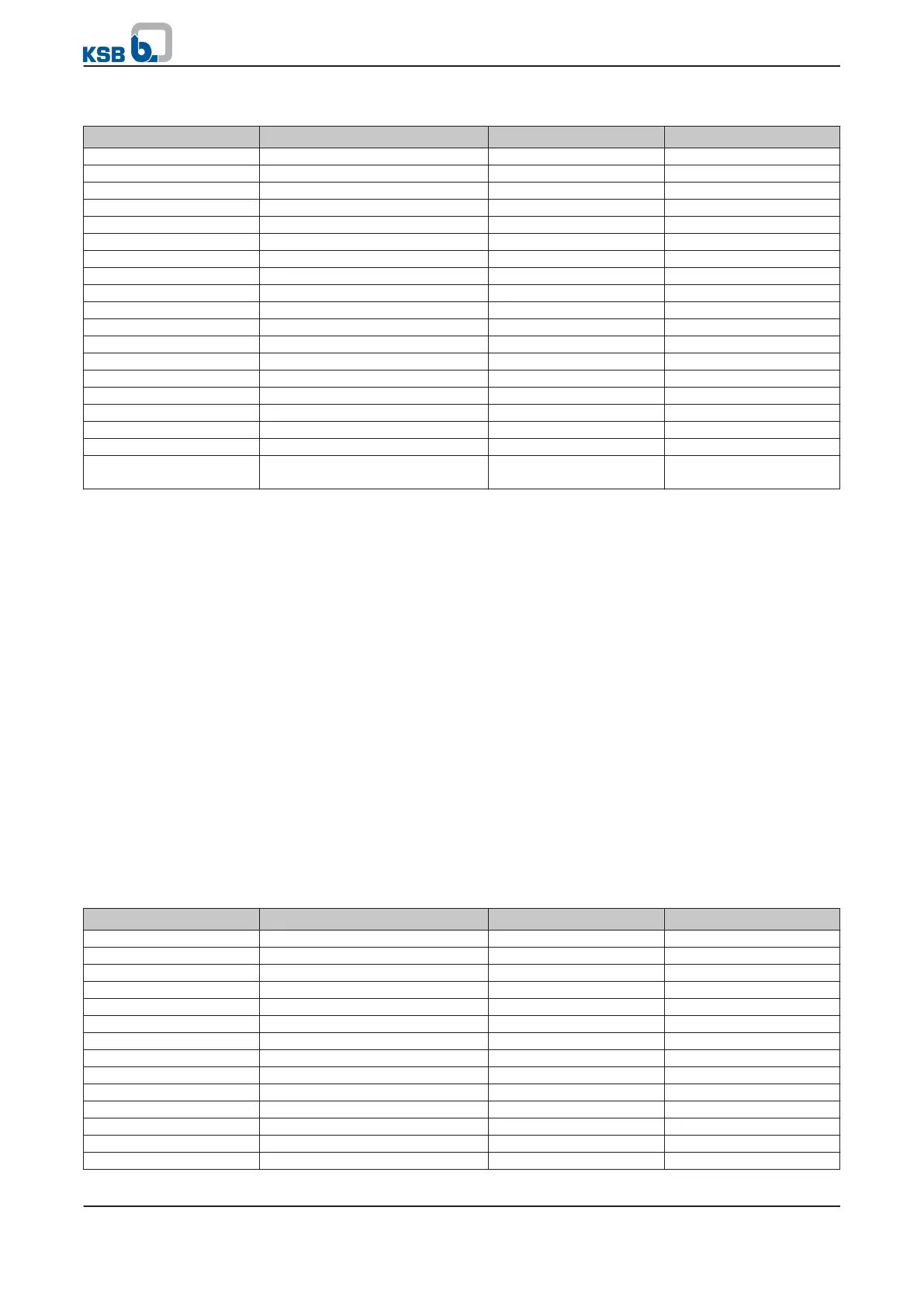
Table 56: Sample parameters for closed-loop control mode using the control panel
Parameter Description Settings Factory setting
3-2-2-1
Physical unit of setpoint bar %
3-2-2-3
Physical unit of pressure bar %
3-5-1-2
Minimum setpoint 0 bar 0 %
3-5-1-3
Maximum setpoint 10 bar 100 %
3-5-4-1
Setpoint source 1 None Analog IN 1
3-5-4-2
Setpoint source 2 Configurable Setpoint Configurable Setpoint
3-5-4-3
Setpoint source 3 None Remote Setpoint
3-5-2-1
Configurable Setpoint 6,7 bar 0 %
3-8-3-1
Configuration of analog input 2 Current Current
3-8-3-2
Analog IN 2 Low current 4 mA 4 mA
3-8-3-3
Analog IN 2 High current 20 mA 20 mA
3-8-3-4
Unit of Analog IN 2 bar %
3-8-3-5
Low value for Analog IN 2 0 bar 0 %
3-8-3-6
High value for Analog IN 2 10 bar 100 %
3-9-1-6
PI Auto mode Disabled Enabled
3-9-1-1
Disable/enable PI controller Enabled Disabled
3-9-1-4
Control direction of PI controller Negative Negative
3-9-1-5
Process type of PI controller Constant pressure Constant pressure
3-9-2-1
Selection of feedback (actual
value) source
Analog IN 2 Analog IN 2
Maintain the following sequence for activating the process controller:
1.
Change parameter
3-9-1-6
.
2. Change parameter
3-9-1-1
.
The value displayed for parameter 1-3-1-3 Setpoint is 6.7 bar.
Parameter 1-3-1-1 for the actual feedback value in the corresponding unit displays
the current actual value.
7.1.1.4.2 Closed-loop control mode with external setpoint signal
By default, analog input 1 (terminal P7:9 AIN1 and 10 AGND P7) is set as the setpoint
source (
3-5-4-1
). A direct voltage of 0 to 10 V (0 to 100 %) is expected as the signal. If
a current signal, e.g. 4 - 20 mA (0 - 100 %) is to be used, the Al 1 Setting parameter
(3-8-2-1)
has to be changed accordingly. Parameters Analog IN 1 Low Voltage
(3-8-2-2)
to Analog IN 1 High Current
(3-8-2-5)
can be used to match the setpoint
input to the signal received.
PumpDrive is to control the system to achieve a setpoint of 6.7 bar in a differential
pressure control process. For this purpose, a differential pressure sensor (4 - 20 mA)
with a measuring range of 0 to 10 bar is connected to analog input 2 of PumpDrive.
The setpoint is specified using an external setpoint signal (4 - 20 mA) via analog
input 1. For the desired setpoint of 6.7 bar, 10.72 mA must be applied at analog
input 1.
Table 57: Parameters for closed-loop control mode using an external setpoint signal
Parameter Description Possible settings Factory setting
3-2-2-1
Physical unit of setpoint bar %
3-2-2-3
Physical unit of pressure bar %
3-5-1-2
Minimum setpoint 0 bar 0 %
3-5-1-3
Maximum setpoint 10 bar 100 %
3-5-4-1
Setpoint source 1 Analog IN 1 Analog IN 1
3-5-4-2
Setpoint source 2 None Configurable Setpoint
3-5-4-3
Setpoint source 3 None Remote Setpoint
3-8-2-1
Configuration of analog input 1 Current Current
3-8-2-2
Analog IN 1 Low current 4 mA 4 mA
3-8-2-3
Analog IN 1 High current 20 mA 20 mA
3-8-2-4
Unit of Analog IN 1 bar %
3-8-2-5
Low value for Analog IN 1 0 bar 0 %
3-8-2-6
High value for Analog IN 1 10 bar 100 %
3-8-3-1
Configuration of analog input 2 Current Current
Example
7 Commissioning/shutdown
60 of 162
PumpDrive