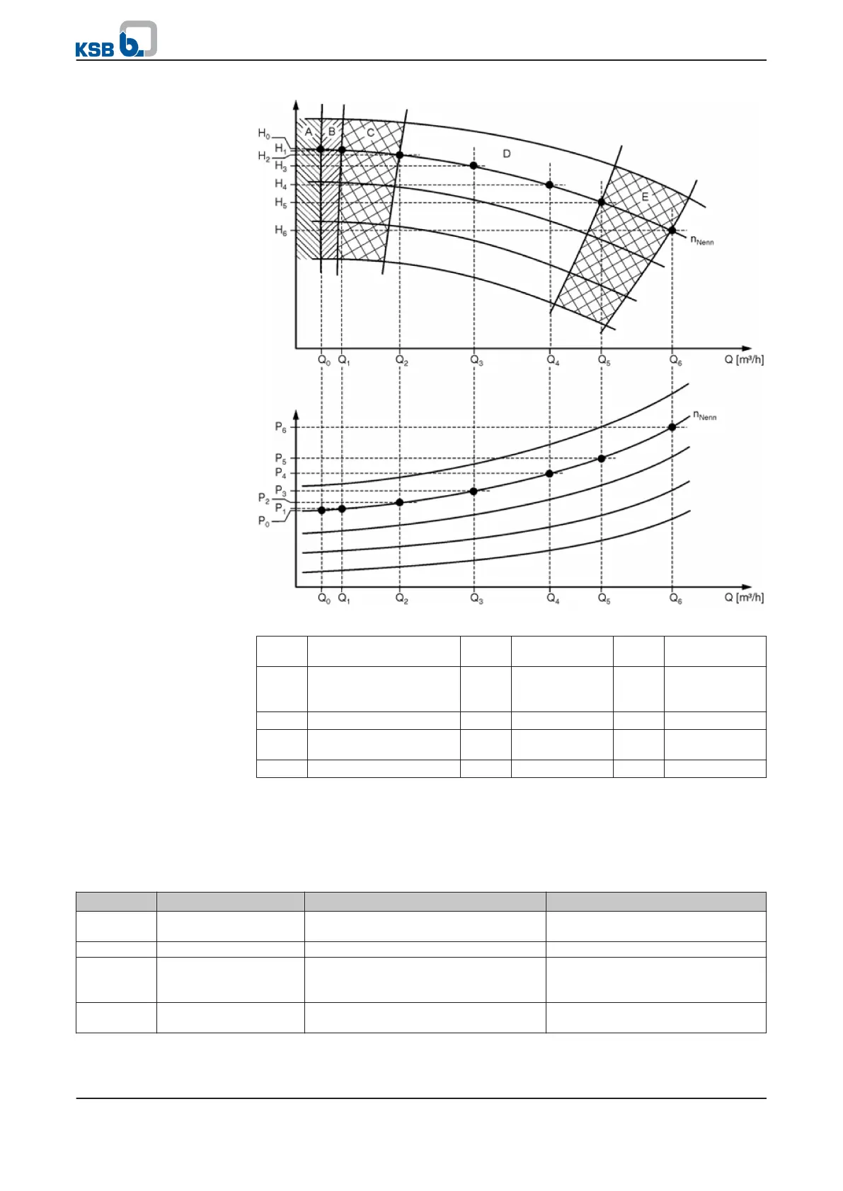
Fig. 44: Pump characteristic curves
A Dry running (⇨ Section
7.2.1.10 Page 75)
Q1 Q
min
Q4 Q
opt
B Hydraulic blockage
(⇨ Section 7.2.1.10 Page
75)
Q2 Q
Low flow
Q5 Q
High flow
C Low flow Q3 Q
<opt
Q6 Q
max
D Continuously
permissible range
E High flow
For characteristic curve control the following parameters must always be set,
irrespective of the method used to determine the flow rate: the H/Q data points and
Q
min
, Q Lim Low Flow, Q
opt
, Q Lim High Flow, and Q
max
for the driven pump. Q Lim
Low Flow must not be lower than Q
min
and Q Lim High Flow must not be higher than
Q
max
.
Table 75: Parameters for characteristic curve control
Parameter Description Possible settings Factory setting
3-12-4-1
Q high flow (overload)
limit
0 to 9999 in physical unit for 3-2-2-2 Q
Unit
100 m³h
3-12-4-2
Q Hi Timeout Time 0..120 (s) 20 s
3-12-4-3
Q High flow timeout
function
No Function
Warning
Stop and Trip
No Function
3-12-4-4
Q Low flow limit 0 to 9999 in physical unit for 3-2-2-2 Q
Unit
100 m³h
7 Commissioning/shutdown
PumpDrive
79 of 162