NOTE
Parameters
3-8-2-11
and
3-8-3-11
must not both be set to "Q" at the same time.
Table 96: Parameter(s) for dynamic pressure compensation function on a PumpDrive Advanced model using flow
rate measurement via a sensor
Parameter Description Settings
3-9-1-5
Process type of PI controller Variable pressure
3-4-1-1
Q measurement/estimate Measured
3-12-1-1
Q measurement Measured
3-4-1-2
Calibration for Q measurement, Q 100 % value Full-scale value of flow rate sensor
3-4-1-3
Calibration for Q measurement, p 100 % value Full-scale value of pressure/differential pressure
sensor
3-4-2-1
Q compensation point As required by system conditions
3-4-2-2
Setpoint compensation
For connection of the flow rate sensor to analog input 1:
3-8-2-11
AI 1 descriptor Q
For connection of the flow rate sensor to analog input 2
3-8-3-11
AI 2 descriptor Q
7.2.4.2 Stand-by mode (sleep mode)
NOTE
In stand-by (sleep) mode, PumpDrive may start up without any warning if the actual
pressure exceeds the defined hysteresis for closed-loop control mode
(3-4-3-2)
.
When the pressure is controlled, PumpDrive will recognise whether the flow rate
supplied is actually used. If there is no demand, PumpDrive will stop at a user-
definable minimum speed and will only restart once the pressure in the accumulator
falls, i.e. when there is actual demand from the system.
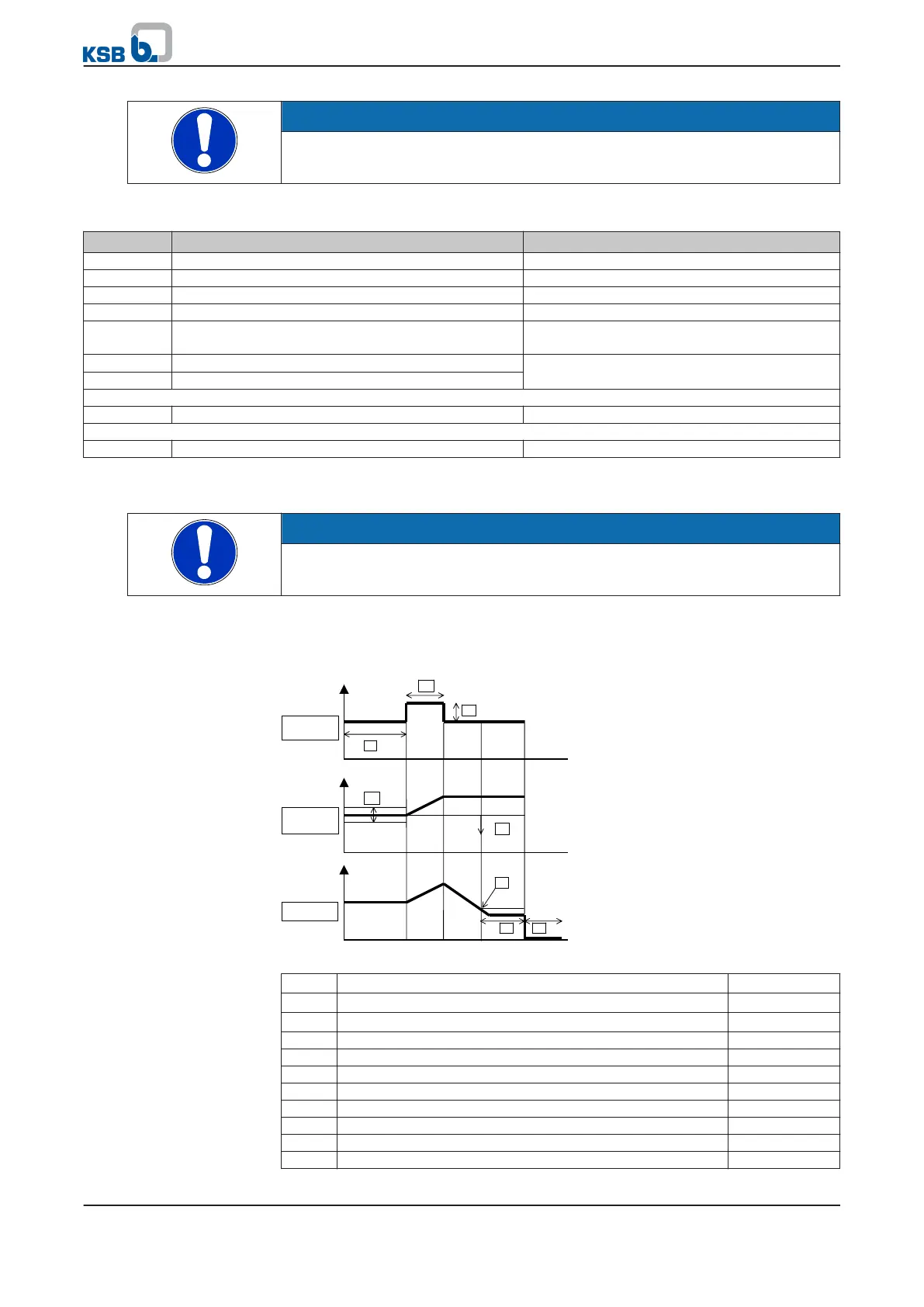
Fig. 46: Time characteristics of parameters for stand-by (sleep) mode
A Pressure setpoint
B Pressure actual value
C Speed
1 Waiting time until activation
3-4-3-6
2 Duration of test pulse
3-4-3-9
3 Setpoint increase/pulse
3-4-3-8
4 Hysteresis for closed-loop control mode
3-4-3-2
5 Hysteresis for pressure variations
3-4-3-7
6 Minimum speed before stopping
3-4-3-4
7 Waiting time before stopping
3-4-3-5
8 Waiting time before system start-up
3-4-3-3
7 Commissioning/shutdown
PumpDrive
89 of 162