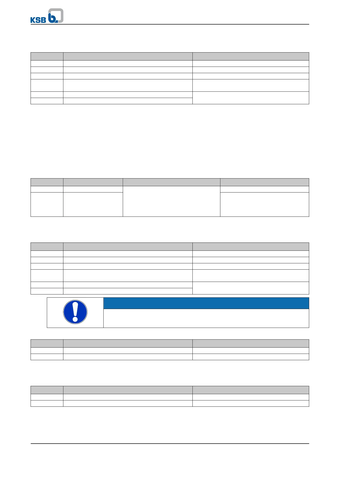
Table 91: Parameterisation for the dynamic pressure compensation function on a PumpDrive Advanced model using
flow rate estimation based on the power
Parameter Description Settings
3-9-1-5
Process type of PI controller Variable Pressure
3-4-1-1
Q measurement/estimate Measured
3-12-1-1
Q measurement P/Q calculated
3-4-1-3
Calibration for Q measurement, p 100 % value Full-scale value of pressure/differential pressure
sensor
3-4-2-1
Q compensation point As required by system conditions
3-4-2-2
Setpoint compensation
Parameters
3-12-3-7
to
3-12-3-20
for the pump's H/Q curve described in section must
be set for parameterisation of the dynamic pressure setpoint compensation function
on a PumpDrive Advanced model using flow rate estimation based on the
differential pressure. Also read the information provided in the relevant section for
parameterising the flow rate estimation function (⇨ Section 7.2.2.3.1 Page 80) . The
differential pressure measurement can either be effected by a differential pressure
sensor or two pressure sensors in the discharge-side and suction-side piping.
Therefore, the following parameters are required in addition to the parameters listed
for defining the analog inputs:
Table 92: Parameterisation for the dynamic pressure setpoint compensation function on a PumpDrive Advanced
model using flow rate estimation based on the differential pressure
Parameter Description Possible settings Factory setting
3-8-2-11
AI 2 descriptor Process
Pressure P1
Pressure P2
Q
Temperature
Process
3-8-3-11
AI 2 descriptor Process
The parameters must be set as follows:
Table 93: Parameterisation for the dynamic pressure setpoint compensation function on a PumpDrive Advanced
model using flow rate estimation based on the differential pressure
Parameter Description Settings
3-9-1-5
Process type of PI controller Variable pressure
3-4-1-1
Q measurement/estimate Measured
3-12-1-1
Q measurement P/Q calculated
3-4-1-3
Calibration for Q measurement, p 100 % value Full-scale value of pressure/differential pressure
sensor
3-4-2-1
Q compensation point As required by system conditions
3-4-2-2
Setpoint compensation
NOTE
The differential pressure sensor, if used, is always connected to analog input 2. The
AI 1 descriptor parameter
(3-8-2-11)
must not be set to Pressure P1.
Table 94: Parameterisation of analog inputs for connection of a differential pressure sensor
Parameter Description Settings
3-8-2-11
AI 1 descriptor Process
3-8-3-11
AI 1 descriptor Pressure P2
Connection of a suction pressure sensor to analog input 1 and a discharge pressure
sensor to analog input 2.
Table 95: Parameterisation of analog inputs for connection of a suction pressure sensor
Parameter Description Settings
3-8-2-11
AI 1 descriptor Pressure P1
3-8-3-11
AI 1 descriptor Pressure P2
The parameters for parameterisation of the dynamic pressure compensation function
on a PumpDrive Basic model using flow rate measurement via a sensor must be set as
follows:
7 Commissioning/shutdown
88 of 162
PumpDrive