8 ERGONOMICS 76
602628-10
–
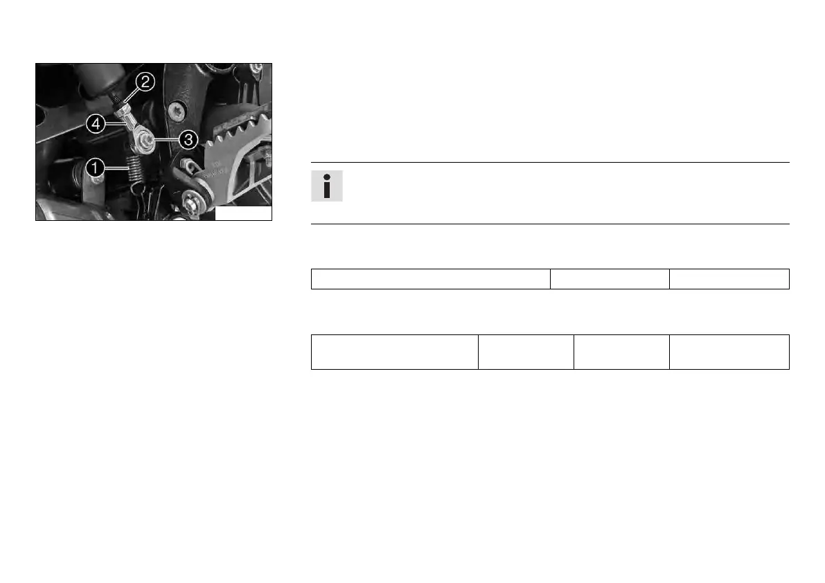
Disconnect spring
1
.
–
Loosen nut
2
.
–
Remove screw
3
.
– To adjust the basic position of the foot brake lever to individual requirements, turn ball
joint
4
accordingly.
Info
The range of adjustment is limited.
The screw must be screwed into the ball joint by at least 5 turns.
–
Hold ball joint
4
and tighten nut
2
.
Guideline
Remaining chassis nuts M6 10 Nm (7.4 lbf ft)
–
Mount and tighten screw
3
.
Guideline
Screw, ball joint of push rod
on foot brake cylinder
M6 10 Nm
(7.4 lbf ft)
Loctite
®
243™
–
Attach spring
1
.

 Loading...