G-19
07-E3B SERIES, WSM
G GENERAL
[6] CHECK POINT OF EVERY 1000 HOURS
Checking Valve Clearance
• Valve clearance must be checked and adjusted when engine
is cold.
1. Remove the high pressure pipes, glow lead, glow plugs and the
cylinder head cover.
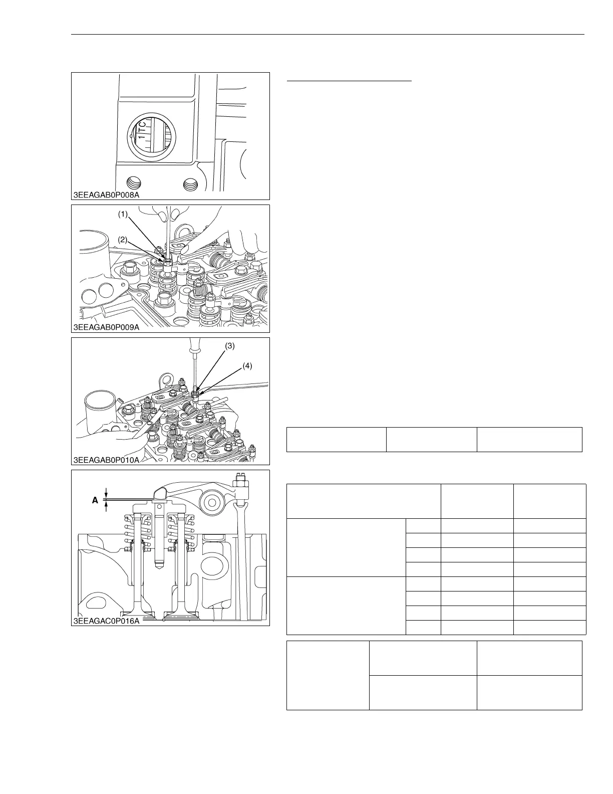
2. Align the 1TC mark of flywheel and the convex of flywheel
housing timing windows so that the first piston (front cover side)
comes to the compression top dead center.
[Adjustable type of valve bridge arm]
(V3007-DI-T-E3B / V3307-DI-T-E3B)
3. Before adjusting the valve clearance, adjust the valve bridge arm
evenly to the valve stem.
4. Loosen the lock nut (2) of adjusting screw (1) and adjust with
screw.
5. Slightly push the rocker arm with your fingers and screw in the
adjusting screw (1) slowly until you feel the screw touch the top
of valve stem, then tighten the lock nut (2).
6. Loosen the lock nut (4) of adjusting screw (3) (push rod side) and
insert the feeler gauge between the rocker arm and the head of
valve bridge arm. Set the adjusting screw (3) to the specified
value, then tighten the lock nut.
[Adjustment unnecessary type of valve bridge arm]
(V2607-DI-E3B / V2607-DI-T-E3B / V3007-DI-T-E3B / V3307-DI-T-
E3B)
3. Loosen the lock nut (4) of adjusting screw (3) (push rod side) and
insert the feeler gauge between the rocker arm and the head of
valve bridge arm. Set the adjusting screw (3) to the specified
value, then tighten the lock nut.
• After adjusting, tighten the lock nut (4) securely.
W1047000
Valve clearance (A) Factory spec.
0.13 to 0.17 mm
0.0052 to 0.0066 in.
Valve arrangement
Adjustment cylinder
Location of piston
IN. EX.
When No.1 piston is at
compression top dead center
1st
2nd
3rd
4th
When No.1 piston is at
overlap position
1st
2nd
3rd
4th
Tightening torque
Cylinder head cover screw
9.81 to 11.2 N·m
1.00 to 1.15 kgf·m
7.24 to 8.31 lbf·ft
Injection pipe retaining nut
23 to 36 N·m
2.3 to 3.7 kgf·m
17 to 26 lbf·ft
(1) Adjusting Screw
(2) Lock Nut
(3) Adjusting Screw
(4) Lock Nut
A : Valve Clearance
 Loading...