S-45
07-E3B SERIES, WSM
ENGINE
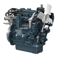
(4) Cylinder Head and Valves
Cylinder Head Cover
1. Remove the glow lead (4) and the glow plugs (3).
2. Remove the injection pipes (1).
3. Remove the cylinder head cover (2).
(When reassembling)
• Check to see that the cylinder head cover gasket is not detective.
• Tighten the head cover mounting screws to specified torque.
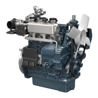
• Check the position of the injection pipe clamps (5) to reduce the
vibration of the injection pipes (1). (See the figure.)
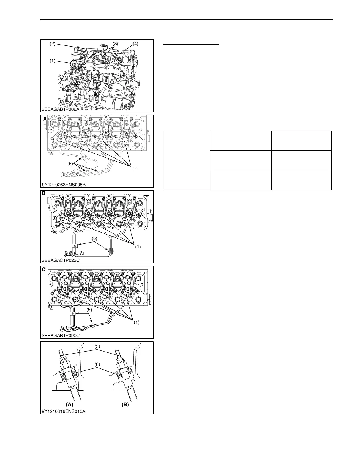
• Adjust the direction of the ditch to the terminal side when the seal
(6) is installed in the glow plug (3).
• After installing the glow plug (3), confirm that the seal (6) was set
to the specified position.
W1021753
Tightening torque
Cylinder head cover screw
9.81 to 11.2 N·m
1.00 to 1.15 kgf·m
7.24 to 8.31 lbf·ft
Injection pipe retaining nut
23 to 36 N·m
2.3 to 3.7 kgf·m
17 to 26 lbf·ft
Glow plug
7.7 to 9.3 N·m
0.78 to 0.95 kgf·m
5.7 to 6.8 lbf·ft
(1) Injection Pipe
(2) Cylinder Head Cover
(3) Glow Plug
(4) Glow Lead
(5) Injection Pipe Clamp
(6) Seal
A : V2607-DI-E3B
B : V2607-DI-T-E3B
C : V3007-DI-T-E3B / V3307-DI-T-E3B
(A) Good
(B) Bad
 Loading...