M-17
07-E3B SERIES, WSM
ENGINE
6. INTAKE AND EXHAUST SYSTEM
[1] TURBOCHARGER
W10353780
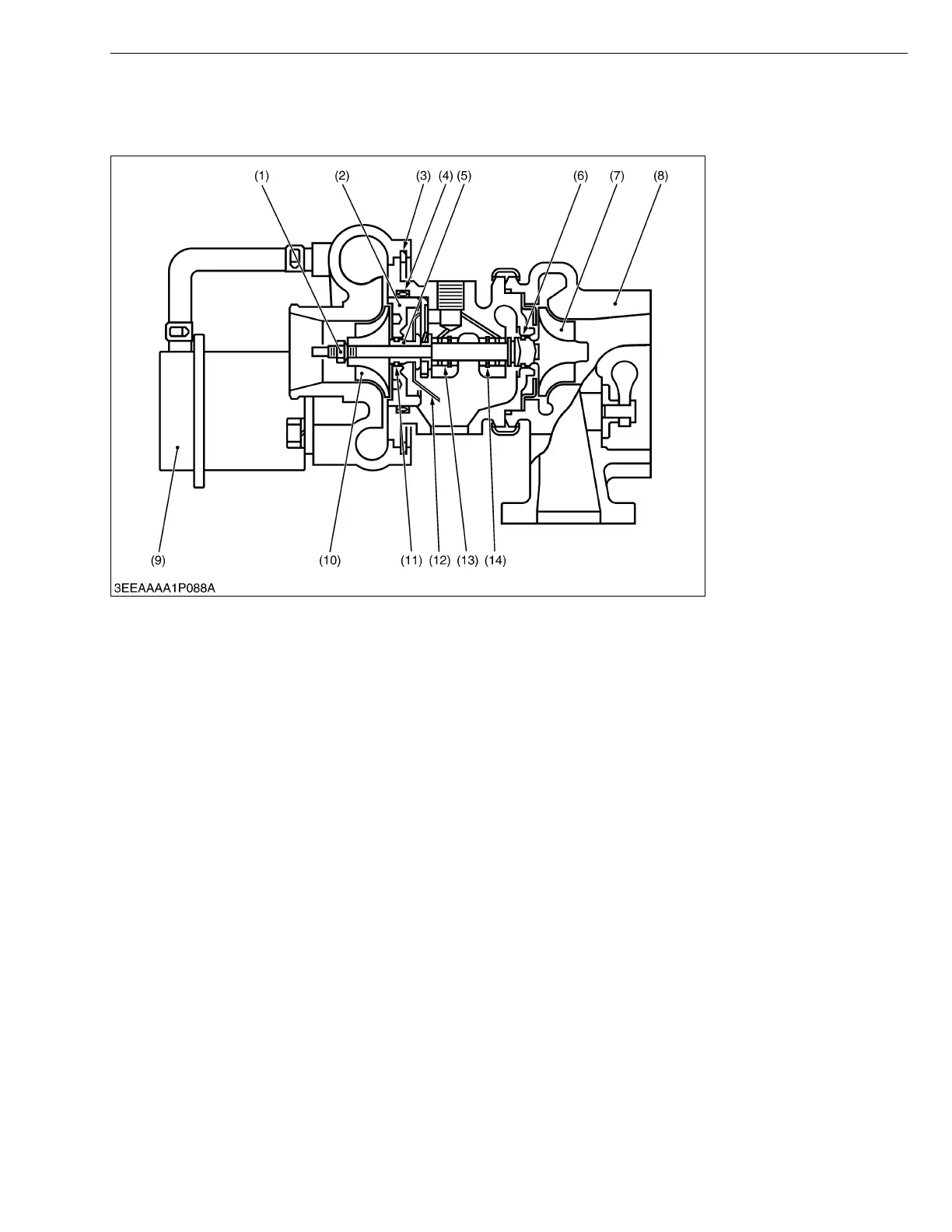
A turbocharger consists basically of a centrifugal compressor mounted on a common shaft with a turbine driven by
exhaust gas. The compressor is usually located between the air cleaner and the intake manifold (or intercooler; if
equipped), while the turbine is located between the exhaust manifold and the muffler.
The prime job of the turbocharger is, by compressing the air, to force more air into the engine cylinders. This allows
the engine to efficiently burn more fuel, thereby producing more horsepower.
In applications where the boost pressure is relatively low, the turbocharger is capable of reducing the smoke
concentration, the concentration in the cylinder, fuel consumption, and deterioration in performance at elevated terrain
by increasing the amount of air into the engine cylinders.
In applications where the boost pressure is high, the turbocharger is capable of providing a large increase in engine
output by increasing the amount of air into the engine cylinders.
(1) Lock Nut
(2) Thrust Bearing
(3) Snap Ring
(4) O-ring
(5) Thrust Sleeve
(6) Piston Ring
(7) Turbine Wheel
(8) Turbine Housing
(9) Actuator
(10) Compressor Wheel
(11) Piston Ring
(12) Oil Deflector
(13) Bearing
(14) Snap Ring
 Loading...