57 / 125Issued: 16.03.2016 Version: MA KR 300 470-2 PA V5
6 Planning
6.3 Machine frame mounting
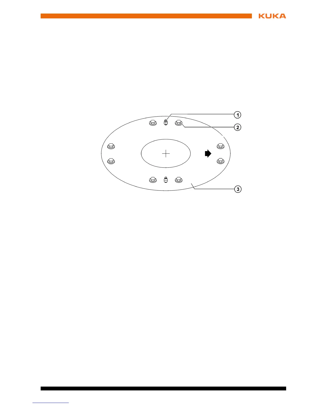
Description The machine frame mounting assembly (>>> Fig. 6-7 ) with centering is used
when the robot is fastened on a steel structure, a booster frame (pedestal) or
a KUKA linear unit. It must be ensured that the substructure is able to with-
stand safely the forces occurring during operation (foundation loads). The fol-
lowing diagram contains all the necessary information that must be observed
when preparing the mounting surface.
The machine frame mounting assembly consists of (>>> Fig. 6-8 ):
Pin with fasteners
Sword pin with fasteners
Hexagon bolts with conical spring washers
Fig. 6-7: Machine frame mounting
1 Pin, sword pin 3 Mounting surface
2 Hexagon bolt (8x)
 Loading...


