69 / 125Issued: 16.03.2016 Version: MA KR 300 470-2 PA V5
8 Start-up and recommissioning
8.3 Installing the machine frame mounting assembly
Description The machine frame mounting assembly with centering (>>> Fig. 6-8 ) is used
when the robot is fastened on a steel structure, a booster frame (pedestal) or
a KUKA linear unit. It must be ensured that the substructure is able to with-
stand safely the forces occurring during operation (foundation loads). The fol-
lowing diagram contains all the necessary information that must be observed
when preparing the mounting surface.
For further data concerning the machine frame mounting assembly, see
(>>> Fig. 8-7 ).
The machine frame mounting assembly consists of:
Pin with fasteners
Sword pin with fasteners
Hexagon bolts with conical spring washers
Preconditions
Substructure and mounting surface are prepared as described in Section
(>>> 6.3 "Machine frame mounting" Page 57).
Procedure for
installation
1. Insert the pin on the left and fasten it with an M8x55-8.8 Allen screw and
conical spring washer.
2. Insert the sword pin on the right and fasten it with an M8x55-8.8 Allen
screw and conical spring washer.
3. Tighten both M8x55-8.8 Allen screws with a torque wrench (M
A
= 23.0
Nm).
8.4 Installing the robot
Description This description is valid for the installation of floor-mounted robots with the as-
semblies “Mounting base for 175 mm, 200 mm concrete thickness” and the
“Machine frame mounting” assembly. 8 hexagon bolts with conical spring
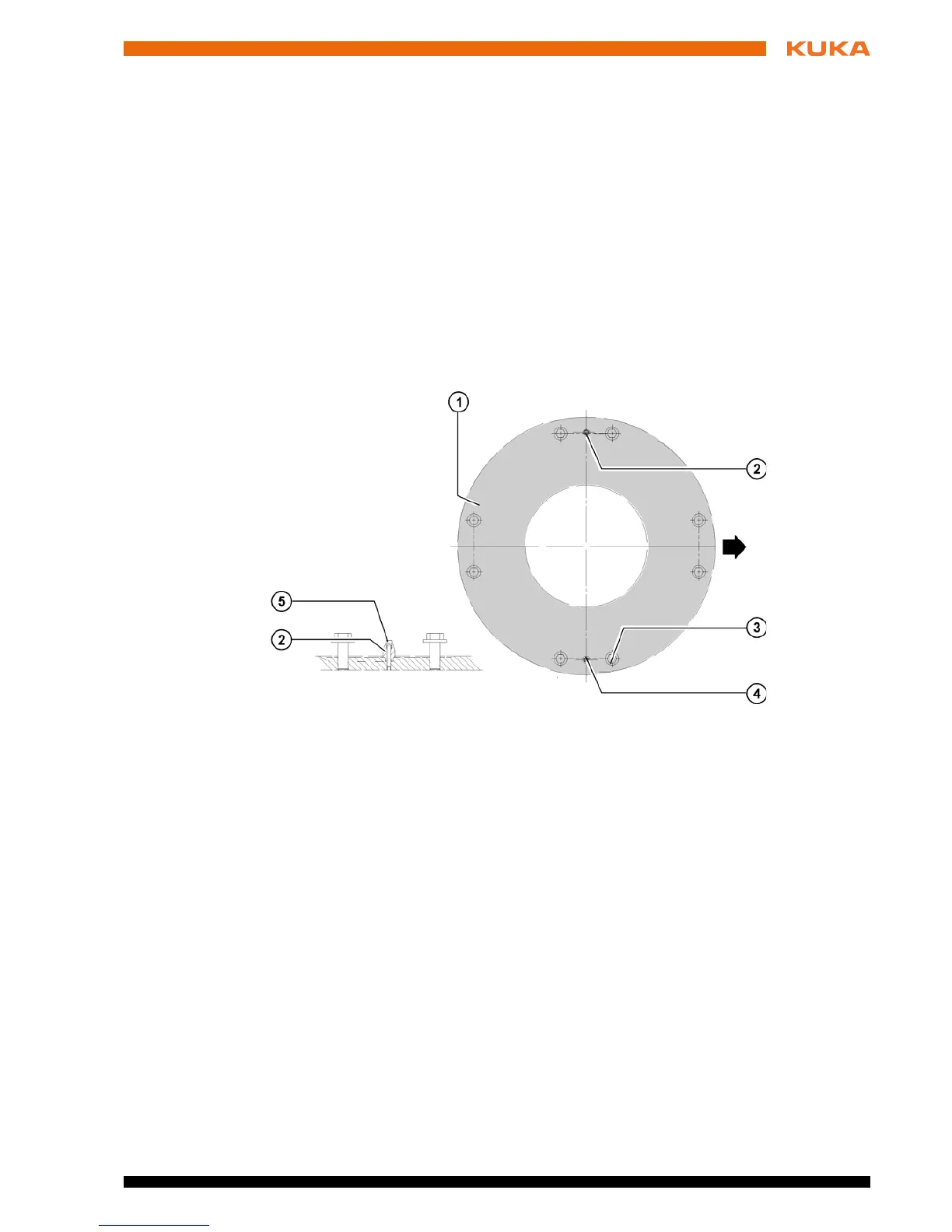
Fig. 8-7: Installing the mounting base
1 Mounting surface 4 Sword pin
2 Pin 5 Allen screw, 2x
3 Allen screw, 8x

 Loading...


