58 / 125 Issued: 16.03.2016 Version: MA KR 300 470-2 PA V5
KR 300-2 PA, KR 470-2 PA
6.4 Connecting cables and interfaces
Connecting
cables
The connecting cables comprise all the cables for transferring energy and sig-
nals between the robot and the robot controller. They are connected to the ro-
bot on the two multi-function housings and the RDC box by means of
connectors (>>> Fig. 6-9 ). The set of connecting cables comprises:
Motor cable X20.1 - X30.1
Motor cable X20.4 - X30.4
Control cable X21 - X31
Ground conductor, optional
Depending on the specification of the robot, various connecting cables are
used. Cable lengths of 7 m, 15 m, 25 m and 50 m are available. The maximum
length of the connecting cables must not exceed 50 m. Thus if the robot is op-
erated on a linear unit which has its own energy supply chain these cables
must also be taken into account.
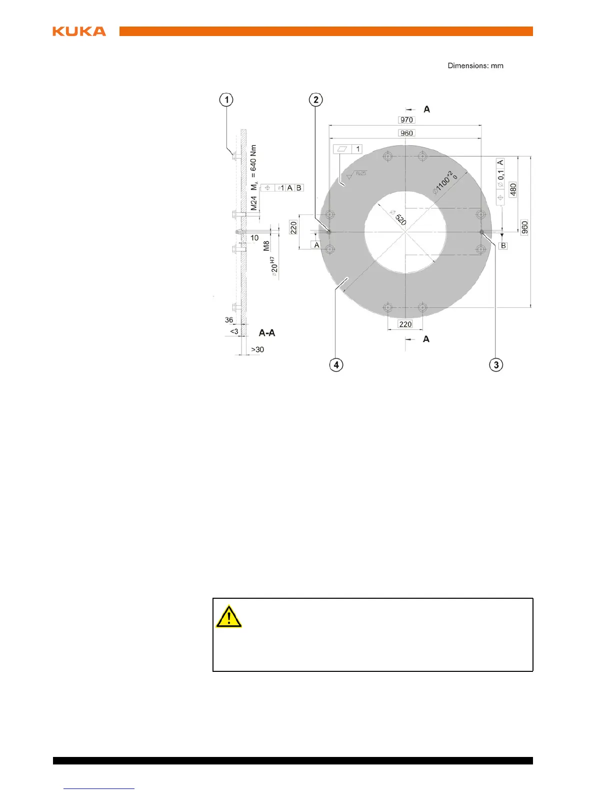
Fig. 6-8: Machine frame mounting, dimensioned drawing
1 Hexagon bolt (8x) 3 Pin
2 Sword pin 4 Mounting surface
For the connecting cables, a ground conductor is always required to
provide a low-resistance connection between the robot and the con-
trol cabinet in accordance with DIN EN 60204. The ground conductor
is not part of the scope of supply and can be ordered as an option. The con-
nection must be made by the customer. The tapped holes for connecting the
ground conductor are located on the base frame of the robot.
 Loading...


