7 Installation, connection (continued)
67 of 122
MA KR 30, 60 HA, KR C4 04.11.02 en
7.3 Principal loads
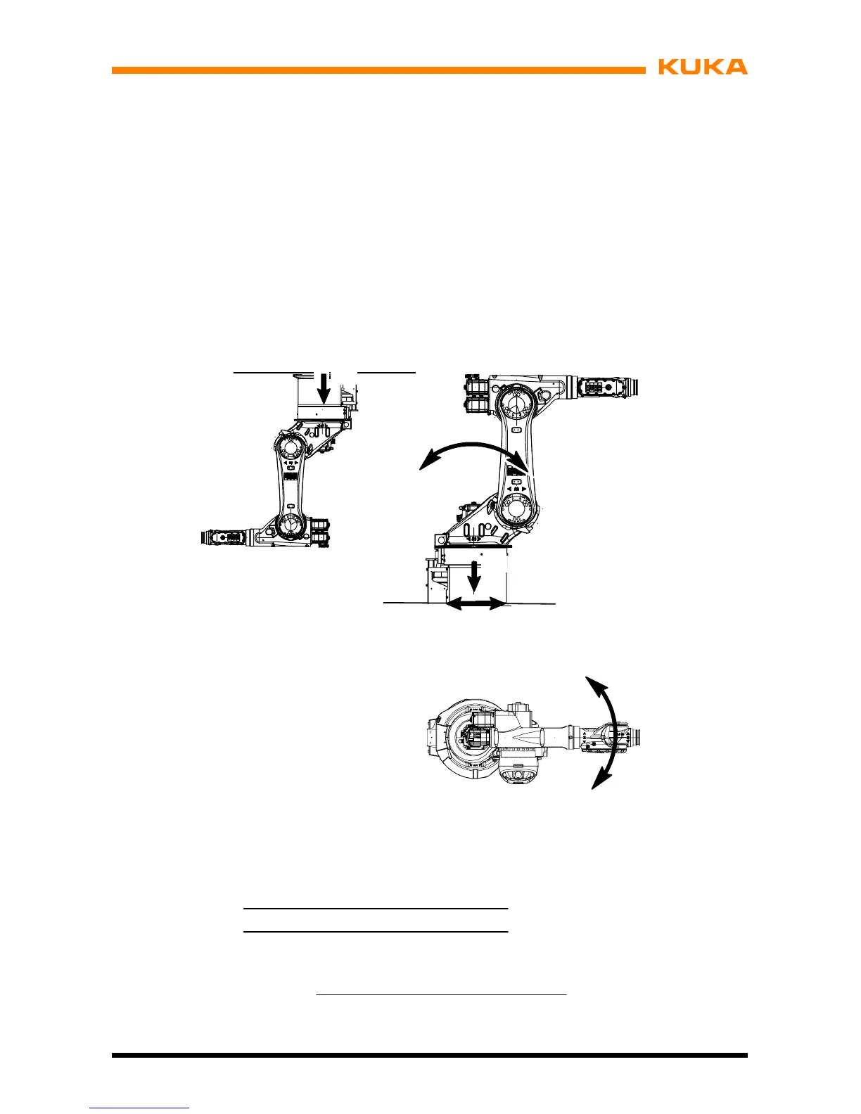
Forces occur during operation of the manipulator which must be safely transmitted to the
floor or ceiling. The forces that have to be taken into account are specified in Fig. 37. The
data given in the illustration can also be used as a basis for more extensive static investiga-
tions.
The specified forces and moments already include the payload and the inertia force (weight)
of the manipulator.
Maximum load Normal load
F
v
= Vertical force F
vmax
= 13 600 N F
v normal
= 9 000 N
F
h
= Horizont force F
hmax
= 12 300 N F
h normal
= 6 950 N
M
k
= Tilting moment M
kmax
= 21 600 Nm M
k normal
= 11 900 Nm
M
r
= Turning moment about axis 1 M
rmax
= 18 400 Nm M
r normal
= 6 850 Nm
Total mass = robot + total load for type
665kg + 65kg KR30HA
665kg + 95kg KR60HA
671 kg + 80 kg KR 60 L45 HA
679 kg + 65 kg KR 60 L30 HA
F
v
F
h
M
k
M
r
F
v
Fig. 37 Principal loads acting on floor (or ceiling) due to manipulator
and total load
 Loading...


