1
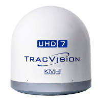
TracVision Antenna Systems
Addendum
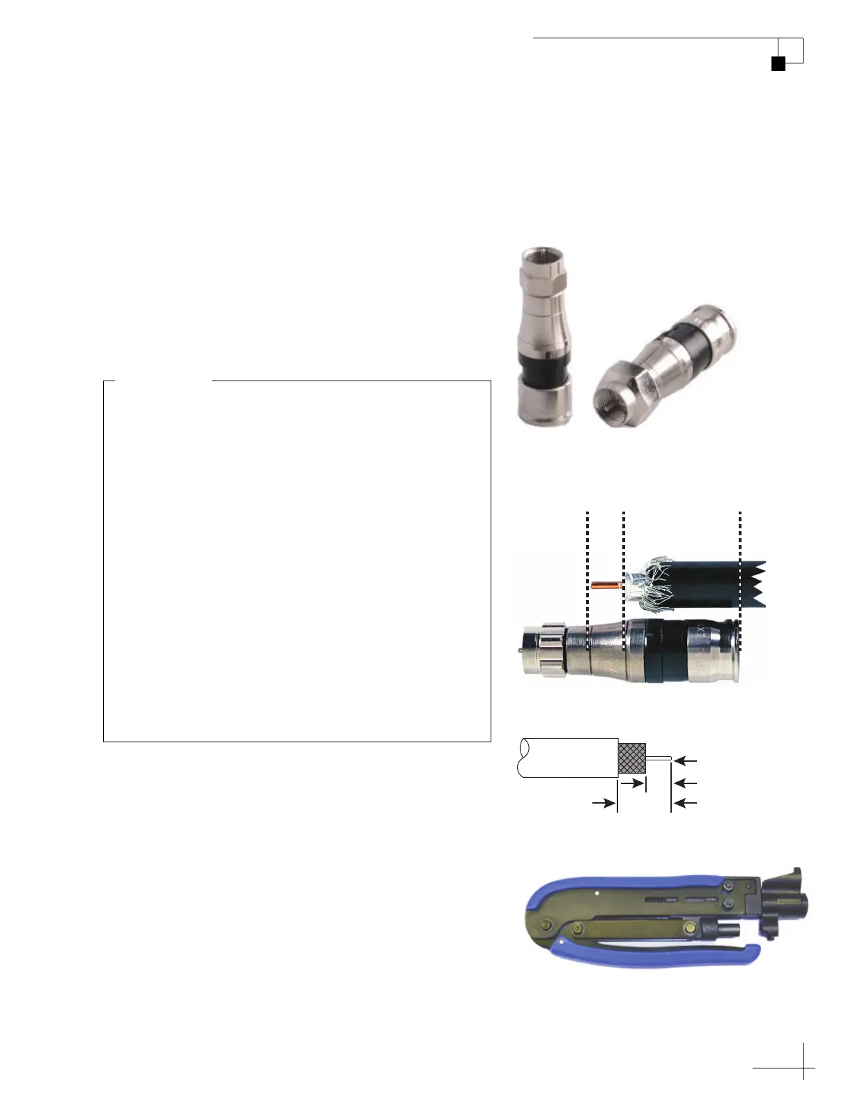
Figure 1: New EX Series 11 Connectors for RG-11
Figure 2: Align the Cable With the Connector
Align with
the end of
the center
conductor
Align with the
base of the
connector
Align with
the end of
the cable
Figure 3: Cable Strip Lengths
0.312" (7.93 mm)
0.562" (14.3 mm)
0.064" (1.63 mm) dia.
Figure 4: New Compression Tool
PLEASE READ!
Important Addendum to the Installation Guide
New RG-11 Cable Connectors
The Belden Snap N Seal connectors (SNS11AS), used to
terminate RG-11 RF cables as described in your antenna
installation manual, are no longer available. KVH has
validated the PPC Belden-brand EX
®
series 11 universal
compression cable connectors as a suitable replacement
(see Figure 1).
New RG-11 Compression Tool
Prepare your cables with the tools provided in the RG-11
crimp tool kit (KVH part no. 72-0493) to ensure that the
cables are stripped to the correct length for proper
engagement between the cable and connector (see
Figure 3). Use the Belden CST596711 cable stripper tool
(KVH part no. 19-0719) to prepare your cables, then
compress the connectors with the new VT200 compression
tool (KVH part no. 19-1141-0200) (see Figure 4). When
compression is complete, the center conductor should be
rigid. If the pin can move in or out, cable performance
may be degraded.
54-1338 Rev. A
The EX series 11 universal connectors differ slightly
from the Sna
p N Seal connectors, so it is critical that
you follow the installation instructions
Be sure to adhere to the following steps, in particular:
1. After folding back your cable’s braid, align
the
center conductor with the grooves on the new
connector’s body. Then mark the cable where it
aligns with the base of the connector (see Figure 2).
2. Insert the cable into the connector. Then push
firmly, while rotating clockwise, until the
connector reaches the mark you made in step 1.
The center conductor should protrude fr
om the
connector nut.
IMPORTANT!
 Loading...