1-5-21
Code Contents
Remarks
Causes Check procedures/corrective measures
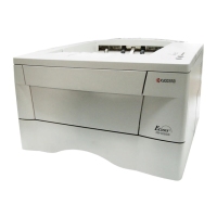
FS-9120DN/9520DN
4200
5300
6000
6020
6050
BD steady-state problem
•While the polygon motor is on, a BD
error is detected three times continu-
ously at 200 ms intervals.
Broken cleaning lamp wire
While the cleaning lamp is on, the bro-
ken cleaning lamp wire detection signal
is detected for 2 s continuously.
Broken fuser heater wire
•When the power is turned on or at the
start of fuser unit control from the
sleep mode, 10 s after fuser heater M
is turned on, the detected tempera-
ture of fuser unit thermistor 2 is lower
than 40 °C/104 °F.
Abnormally high fuser unit ther-
mistor temperature
• Fuser unit thermistor 1 detects tem-
perature 250 °C/482 °F or higher.
• Fuser unit thermistor 2 detects tem-
perature 220 °C/428 °F or higher.
Abnormally low fuser unit thermistor
temperature
• When only fuser heater M is on, fuser
unit thermistor 2 detects temperature
lower than 80 °C/176 °F during print-
ing.
•When fuser heater M and fuser unit
heater S are on, fuser unit thermistor
2 detects temperature lower than 80
°C/176 °F or fuser unit thermistor 1
detects temperature lower than 100
°C/212 °F during ptinting.
Defective laser
diode.
Defective polygon
motor.
Defective engine
controller PWB.
Defective cleaning
lamp.
Defective engine
controller PWB.
Poor contact in
the fuser unit ther-
mistor 1 or 2 con-
nector terminals.
Fuser unit ther-
mistor 1 or 2 in-
stalled incorrectly.
Fuser unit thermo-
stat triggered.
Fuser heater M or
S installed incor-
rectly.
Broken fuser
heater M or S
wire.
Shorted fuser unit
thermistor 1 or 2.
Broken fuser unit
heater control cir-
cuit on the power
supply unit.
Poor contact in
the fuser unit ther-
mistor 1 or 2 con-
nector terminals.
Broken fuser unit
thermistor 1 or 2
wire.
Fuser unit ther-
mistor 1 or 2 in-
stalled incorrectly.
Fuser unit thermo-
stat triggered.
Fuser heater M or
S installed incor-
rectly.
Replace the LSU (see page 1-6-11).
Replace the LSU (see page 1-6-11).
Replace the engine controller PWB and
check for correct operation.
Replace the cleaning lamp.
Replace the engine controller PWB and
check for correct operation.
Check the connection of connector YC10
on the engine controller PWB and the con-
tinuity across the connector terminals. Re-
pair or replace if necessary.
Check and reinstall if necessary.
Check for continuity. If none, replace the
fuser unit thermostat.
Check and reinstall if necessary.
Check for continuity. If none, replace the
fuser heater M or S (see page 1-6-20).
Measure the resistance. If it is 0 Ω, replace
the fuser unit thermistor 1 or 2 (see page
1-6-22).
Replace the power supply unit.
Check the connection of connector YC10
on the engine controller PWB and the con-
tinuity across the connector terminals. Re-
pair or replace if necessary.
Measure the resistance. If it is ∞ Ω, replace
the fuser unit thermistor 1 or 2 (see page
1-6-22).
Check and reinstall if necessary.
Check for continuity. If none, replace the
fuser unit thermostat.
Check and reinstall if necessary.

 Loading...

