FS-9120DN/9520DN
2-1-13
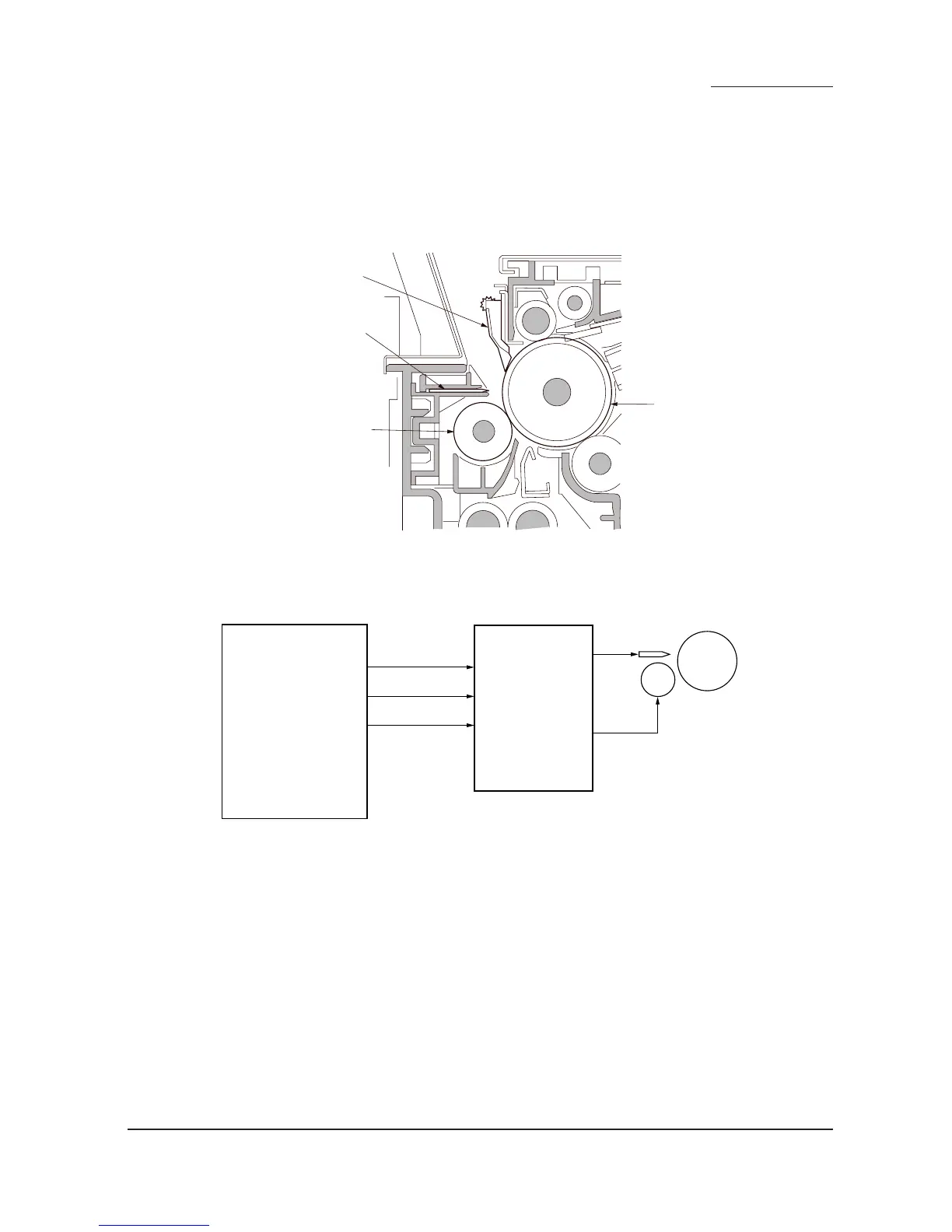
2-1-5 Transfer and separation sections
The transfer and separation section consists mainly of the transfer roller, separation electrode and drum separation
claws.
A high voltage generated by the high-voltage transformer unit (HVTU) is applied to the transfer roller for transfer
charging.
Paper after transfer is separated from the drum by applying separation bias that is output from the high-voltage
transformer unit (HVTU) to the separation electrode.
Drum separation claw
Drum
Separation electrode
Transfer roller
Figure 2-1-16 Transfer and separation sections
TC REM
TC
SC
SC REM
YC1-9
YC1-6
YC7-9
YC7-6
24 V DC
YC1-2YC7-2
EPWB
HVTU
Transfer roller
Separation
electrode
Drum
Figure 2-1-17 Transfer and separation sections block diagram
 Loading...