31
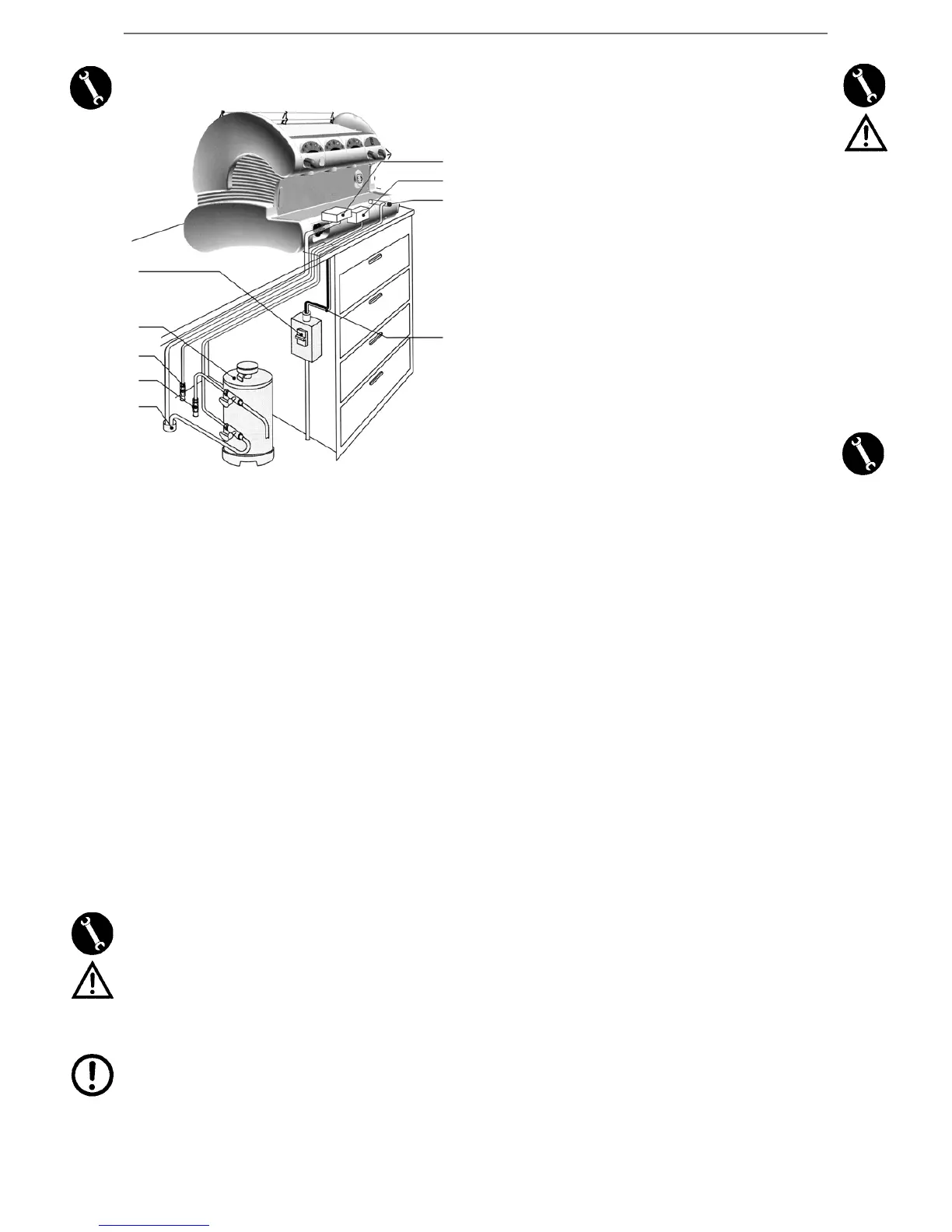
A
C
D
E
F
B
G
I
H
5 - INSTALLATION
A. WATER SYSTEM
B. DRAIN CONDUIT
C. GAS CONDUIT
D. PROTECTION SWITCH
E. SOFTENER
F. BOILER SUPPLY TAP
G. DRAIN BASIN
H. GAS VALVE
I. SUPPLY CABLE
Before starting installation, you need to ensure that:
1. No dents, bumps or buckling exist.
2. No wet areas or other signs exist that may lead to the conclusion
that the packaging has been exposed to bad weather conditions.
3. No tampering signs exist.
Once you have ensured that transport has been carried out correctly,
proceed with installation.
Ensure that the equipment is installed on a flat surface, that can bear
its weight, as well as ensuring that a free area of at least 30 cm is
maintained all around the machine.
Hence proceed with installation operations, in compliance with the
following steps.
5.1 - WATER SYSTEM
Caution! The machine must be supplied with water
having a hardness above 8 F. degrees.
It is advisable to install a water softener for the machine water
system.
Ensure that you will be connecting the machine to drinkable water
mains.
- Connect the softener (E) to the water system (A).
N.B. Before connecting the softener to the machine, carry out
a washing cycle until the water is absolutely clear, after which
you may connect the softener to the machine.
- Connect the drain tray (G) to the drain conduit (B):
- As far as the mains pressure is concerned, if this exceeds 5 bar, it
is advisable to install a balanced pressure reducer for high pressu-
re (a device whereby any mains increase does not affect the output
pressure).
5.2 - ELECTRIC CONNECTION
Caution! Before proceeding with electric connection,
you need to ensure that voltage meets the specifica-
tions shown in the EC. plate.
Ensure that the electric supply line can bear the machine load (see
chapter 4 – Technical Specifications Table).
Provide for an earth connection in compliance with the regulations in
force.
In this regard, ensure that the supply cable is efficient, and that it meets
the national and European safety standards.
The user is to arrange for machine power supply and protect the line
by means of a safety switch (cut-out box) meeting the regulations in
force in the country in question.
Connect the supply cable (I) to the electric line by means of a plug; on
the other hand, in the event of a fixed installation, a multipolar switch
(D) will have to be arranged for network separation, with a distance
between contacts of at least 3 mm.
For voltage change, please refer to the diagram shown on the main
switch box.
The yellow/green coloured cable should be COMPULSORILY connec-
ted to the premises earthing system.
5.3 - GAS CONNECTION
Connect the gas valve (H) to the conduit (C) by means of the hose (in
compliance with the standards in force) and adequate hose clamps, or,
in the event you are using a stainless steel hose, use the specially desi-
gned connection supplied (as shown in the picture under chapter 5.4
“Gas Regulation”).
English








 To Next Page