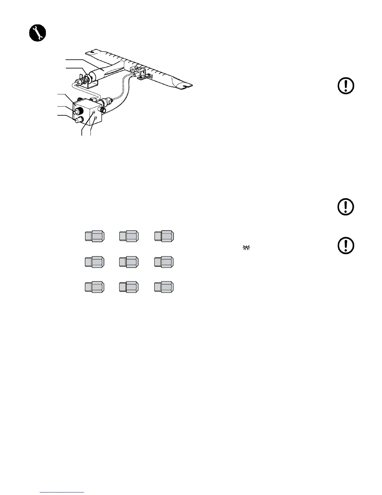
5.4 - GAS REGULATION
5. Gas detection valve
6. Piezoelectric ignition
N. Gas regulation
O. Gas injector
P. Regulation nut
Q. Minimum regulation screw
R. Pressure regulation screw
The machine is designed to be supplied by methane gas (G20),
which means that the gas injector (O) and the gas regulator (N) are
set for methane gas.
For GPL gas (G30 liquefied gas) or town gas operation, the gas
injector (O) needs to be replaced with the corresponding one atta-
ched to the machine (see gas injector table).
Gas burner ignition must be carried out by holding the gas detection
valve button pressed (5), to allow inflow of gas into the burner, and
by then operating the piezoelectric ignition button (6).
N.B. The detection valve button must remain pressed
for a few seconds in order for the thermocouple to
start.
Adjust the airflow by means of the specially provided air regulation
nut (P); by turning it clockwise the flow decreases, by turning it anti-
clockwise the flow increases, so as to achieve a blue-coloured flame
(avoid high or too oxidising flames, which may damage the boiler).
Wait for the boiler to reach a 1.1÷1.3 bar operating pressure and
for the flame to be reduced to a minimum. Should you need to set the
gas regulator (N), proceed as follows: turn the minimum regulation
screw (Q) clockwise to lower the flame and turn it anticlockwise to
increase the flame.
When water temperature drops below the minimum set values with
the machine running, the flame automatically switches back to the
maximum value.
To increase or decrease maximum boiler pressure, operate the pres-
sure regulation screw (R) clockwise to decrease the pressure and
anticlockwise to increase it.
The machine is provided with a gas supply tap complying with the
safety standards that, in the event of accidental flame extinction,
resulting from whatever reason, produces the automatic interruption
of gas outflow. In this case, you need to repeat the ignition operation
as described above.
The machine may provide both for electrical and gas heating, or else
it can be independently heated either electrically or by gas.
When the machine is exclusively gas operated, you need to turn the
main switch (3) on the position, which supplies all the electrical
parts of the machine, with the exception of the heating element.
Category III
1a 2H3+
G20
(methane)
G30
(liquefied gas)
G110
(town gas)
Machine 2 GR. Machine 3 GR. Machine 4 GR.
B
03
1
C
04
2
D
05
3
5
O
6
P
R
N
Q
 Loading...