The FT Series Floor Standing, Combination Boiler
Page 49
NG NGLNG
OI
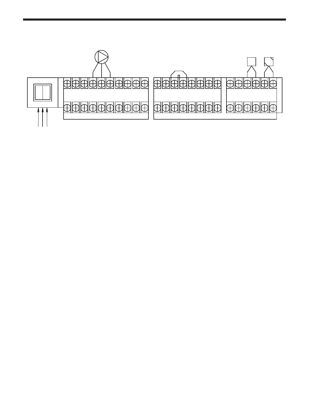
SYSTEM PUMP
LINE VOLTAGE TERMINALS (14 Gauge Wire)
L/ZC
LOW VOLTAGE TERMINALS (18 Gauge Wire)
SYSTEM 1 WIRING
(Factory Installed Jumper)
TSTAT OUTDOOR
SENSOR
SYSTEM PUMP
MAIN POWER
DHW RECIRC PUMP
120 VAC
LESS THAN
12 AMPS.
AC24V
OUTPUT
LWC
DHW
RECIRC.
SENSOR
H-T/T
O/S
R 0-10V W
(+) INPUT (-)
T/T
L
Wiring of a single pump system.
1)
Do not bring 24 V to any terminals on the FTCF boiler. The room thermostat (dry contact only) connects
back to the T/T terminals.
2)
Install the outdoor sensor (OS) for outdoor reset operation.
3)
Connect the system pump as shown above.
Note:
This space is intentionally left blank.



 To Next Page