Page 56
System Control Setting
Maximum ame detecting voltage 2.4V
Pre-purge time (Tp) Maximum 10s, minimum 1s
Safety Time (igniting time) (Ts) 3s
Igniting interval time 10s
Post-purge time (Tip) 120S (1st : 60s + 2nd 60s)
Over-heating 1,2,3 protection detection time <3s
Pump1 post circulating time (T1pv) 60s
Pump2 post circulating time (T1pv) 60s
High & Low Water Level detection time <6s
High & Low Water Level Recover time <6s
800.900.9276 • Fax 800.559.1583 (Customer Service, Service Advisors)
20 Industrial Way, Rochester, NH 03867 • 603.335.6300 • Fax 603.335.3355 (Applications Engineering)
1869 Sismet Road, Mississauga, Ontario, Canada L4W 1W8 • 905.238.0100 • Fax 905.366.0130
www.Laars.com
Document 4388
The FT Series, Wall Combi, Gas Conversion Kit
pg 3 of 4
Gas Valve
Adjustment Port
+
+
-
-
Gas Valve
Adjustment Port
Figure D
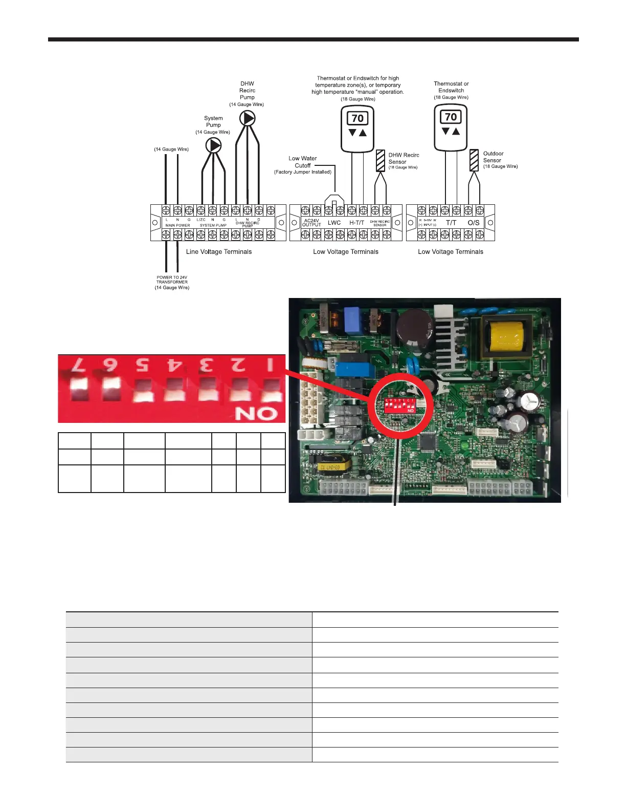
Table B DIP Switch Settings
Shown is a
Model 140
with 3" Venting
and using
Natural Gas
Figures E
MBH
140
199
ON OFF
MIN Fire Normal Operation
MAX Fire Normal Operation
NG Natural LP Propane
3” Vent Size
2” Vent Size
FTCW140
FTCW199
7. Install the new LP (propane) nozzle or orifi ce.
Re-use the packing from previous.
8. Return the Gas Inlet Pipe to its original position
and tighten both brass fi ttings.
9. Per Table B, set DIP Switch 5 to OFF for LP
Propane.
10. Turn ON the GAS and WATER supply to the FT
11. Now start the unit and adjust combustion as
described in Section 4.12
12. Upon completion of set up, write in the correct
Conversion Date and the Technicians Name to
the included gas conversion sticker. See Figure F.
Then apply that sticker adjacent to the rating plate.
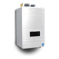
4.21 Dip Switches
Shown is a Model 199 Natural Gas
with 3” Venting.
7* 6* 5 4 3 2 1
OFF OFF LP Gas 2˝ Vent
Low
Fire
High
Fire
Natural
Gas
3˝ Vent
FACTORY SET
*Dip Switches #7 and #6 are Maximum and Minimum re test Switches which are used only when setting up
combustion (See Section 4.13). These switches should only be in the ON position during either High or Low
re testing. When nished testing, ensure both of these switches are in the OFF position.
Dip Switches #1, 2 and 3 are Set at the factory and should not need adjusting. For reference the correct
positions of these three switches are as follows: Model FTCF199: All three dipswitches should be in the
“down”/ ON position (As shown above)
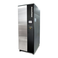
4.20 Electrical Wiring Connections (continued)
 Loading...