The FT Series Floor Standing, Combination Boiler
Page 7
# Name of Component
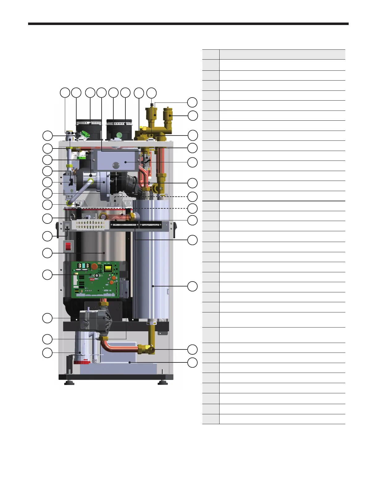
1 Pressure Relief Valve
2 Air Vent (air eliminator)
3 Boiler Return Connection
4 DHW Recirculation Connection
5 Boiler Supply Connection
6 Vent Pipe Collar
7 Boiler Pressure Gauge
8 Cold Water Flow Sensor
9 Air Intake Collar
10 DHW Inlet Connection
11 DHW Outlet Connection
12 DHW Filter and Flow Restrictor
13 Gas Inlet Adapter
14 Air/ Gas Venturi
15 Gas Valve
16 BLDC Fan (Blower)
17 Low Water Cut O
18
Burner High Limit Switch
19 Flame Detecting Sensor
20 Manual Power Switch (ON / OFF)
21 Heat Exchanger
22 Main PCB
23 Boiler Pump
24 Blocked Condensate Switch
25 Condensate Trap
26
Condensate neutralizer and Drain pump
(optional equipment)
27
Drain Valve
28 Low Loss Header and DHW Coil
29 Terminal Block
30 Overheat Temperature Sensor
31 Sight Glass
32
Igniter
33 Exhaust Pipe
34 Control Panel and Display
35 Air Pressure Sensor
2.4 Names of Components
The FT Series Floor Standing, Combination Boiler
Page 7
# Name of Component
1 Pressure Relief Valve
2 Air Vent (air eliminator)
3 ‘CH’ Return Connection
4 DHW Recirculation Connection
5 ‘CH’ Supply Connection
6 Vent Pipe Collar
7 CH Pressure Gauge
8 Flow Sensor
9 Air Intake Collar
10 DHW Inlet Connection
11 DHW Outlet Connection
12 DHW Filter and Flow Restrictor
13 Gas Inlet Adapter
14 Air Gas Mixing Pipe
15 Gas Valve
16 BLDC Fan (Blower)
17 Low Water Cut O
18
Burner High Limit Switch
19 Flame Detecting Sensor
20 Manual Power Switch (ON / OFF)
21 Heat Exchanger
22 Main PCB
23 Boiler Pump
24 Blocked Condensate Switch
25 Condensate Trap
26
Condensate Drain Pump
27 Drain Valve
28 DHW Water Tank
29 Terminal Block
30 Overheat Temperature Sensor
31 Sight Glass
32
Spark Plug
33 Exhust Duct
34 Control Panel and Display
35 Air Pressure Sensor
2.4 Names of Components
15
14
16
17
19
21
22
23
24
25
26
27
28
29
30
31
33
32
34
35
20
18
12
13
2
5 4
3
11 10 9
1
678