Page 50
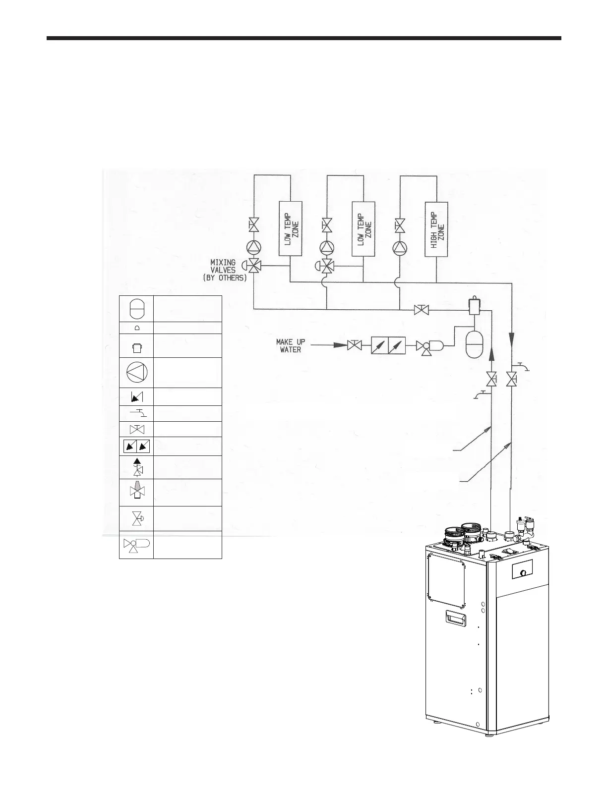
4.16.7 Zoning with multiple pumps
Boiler Supply
Boiler Return
1) This piping diagram is meant to show system piping concept only. Installer
is responsible for all equipment and detailing required by local codes.
2) The minimum pipe size of DHW piping should be 3/4” diameter.
3) Install a minimum of 12 diameters of straight pipe upstream of all
circulators.
4) Manufacturer requires the use of an anti-scald mixing valve at domestic
hot water outlet (boiler location) to reduce potential for scalding. An
approved anti-scald valve is provided in the accessory box. Check with
local codes.
1) In a pump based system, each heating zone has its own circulator pump which run
when the zone demands heat.
2) Each zone thermostat goes to a Pump Relay Panel which controls the pumps. The
dry contact end switch of the relay panel connects back to the T-T terminals on the
FT boiler.
Refer to section 4.15.4 for detailed DHW piping for the FT Floor Combi boiler.
Circulation pump
Check valve
Zone valve
Pressure
reducing valve
Drain valve
Gate valve
Backflow preventer
Pressure Relief Valve
Expansion tank
Air separator
(Diaphragm-type)
Automatic air vent
Anti-scald rated
Mixing Valve
Check Valve
Shut-off valve
Circulation pump
with built-in IFC



 To Next Page