5.3 Control Tab
The Module Control page is selected by tapping the
Control tab in Module View.
The table shown by the Control tab displays data
contained in the Module output channel, and not
the power channels. It is important to remember
that Amplifier Gain and ISVPL data is stored within
each module alongside other data for the Dolby Lake
Module. Appropriate Amplifier Gain and ISVPL data is
transferred to the respective power output channel(s)
when they are routed to the Module outputs.
5.3.1 Power Control
Power On and Standby buttons are provided on the
Control tab. These buttons can control the PLM Frame
(or multiple frames in a Super Module configuration)
containing any power output channels assigned to the
module, allowing the Frame(s) to be set in Standby
mode. A system-wide power control facility is available
from the Control tab in Global View. (See section
5.7.)
5.3.2 Amplifier Gain
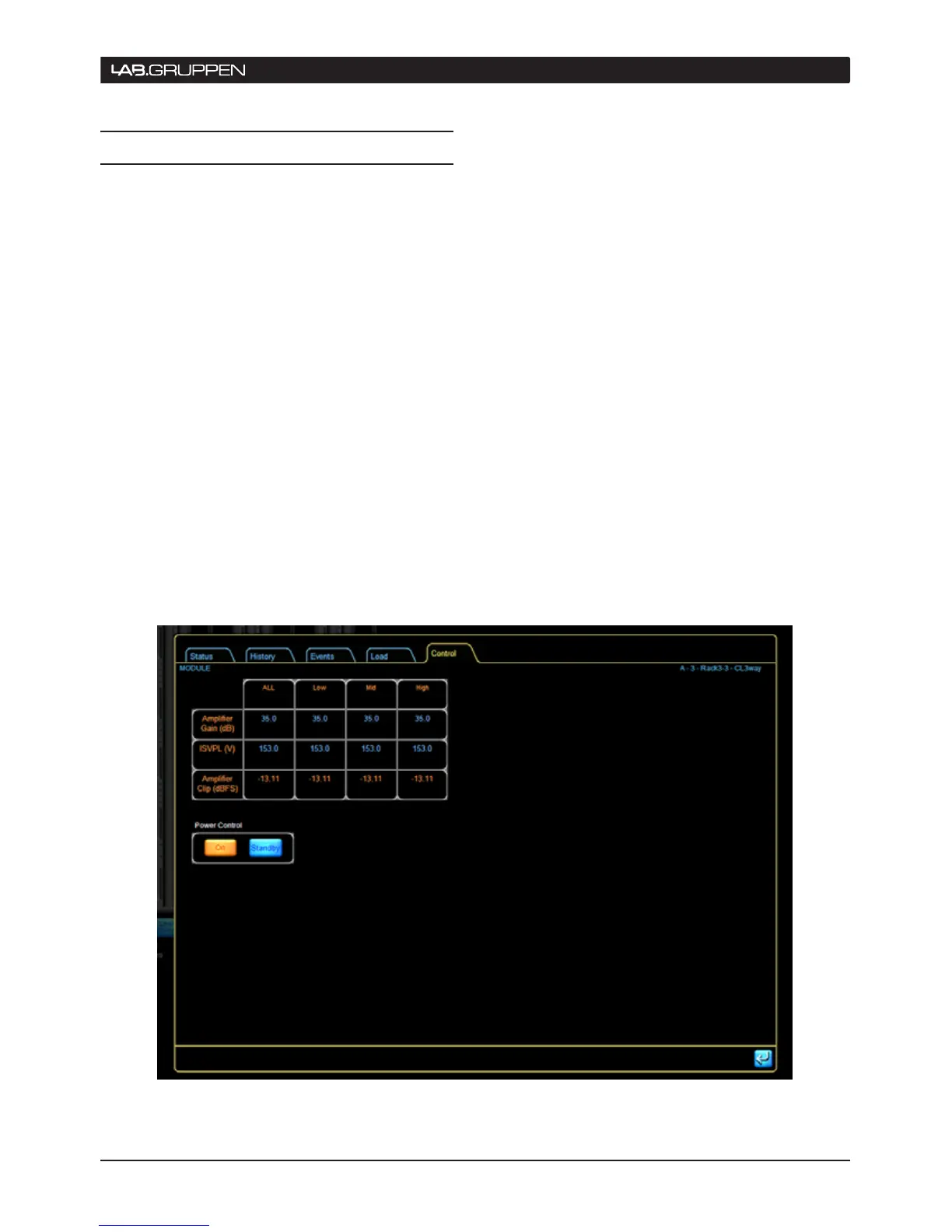
The Module Control tab displays a table showing the
values currently set for Amplifier Gain. The first row of
the table shows the current Amplifier Gain settings.
These may be set by tapping on the table cell and
entering value from the pop-up numeric keypad. The
gain parameter is that of the power output stage.
Entering a value in the ALL cell applies that value to
all power output channels.
Amplifier Gain may also be set via the PLM front
panel at MENU > MODULE > AMP GAIN.
5.3.3 Inter-Sample Voltage Peak Limiter
(ISVPL)
The table’s second row shows the ISVPL threshold as
currently set. These values correspond to the ISVPL
settings adjusted on the PLM front panel via MENU
> MODULE > LIMITERS > ISVPL. Threshold values
may be adjusted on the front panel interface or on
screen in the same manner as above. Amplifier Gain
and ISVPL are subject to limits set by the system
designer. If you are unable to change a value, this may
be due to restrictions set by the system designer for
that parameter. See Section 5.3.5.
Figure 5-3: Control tab with parameters and power control
operation 5
 Loading...