5-26 Echo Liquid Handler User Manual
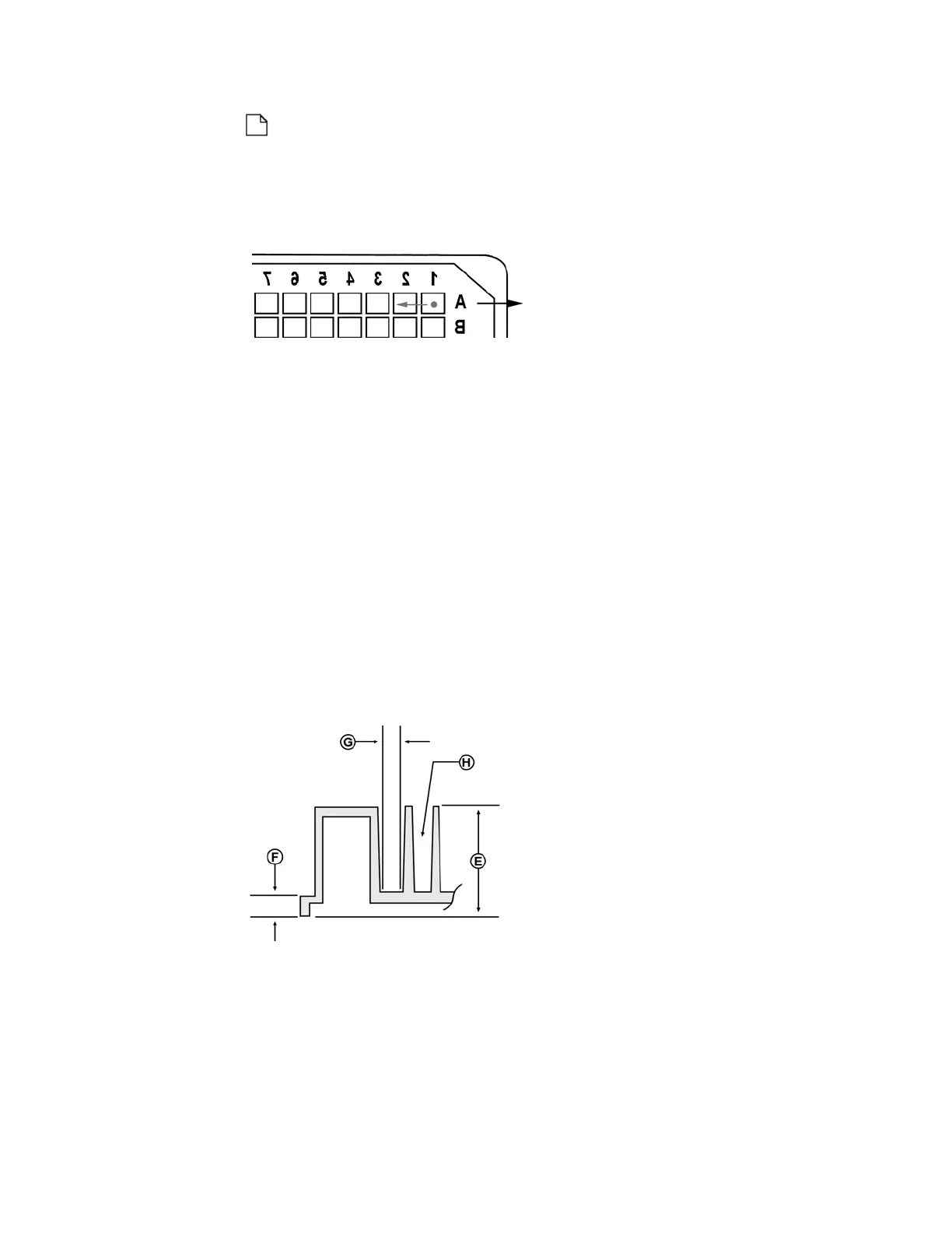
Note: The Echo liquid handler's frame of reference for the destination
is an inverted microplate. Increasing the A1-X offset will shift the
inverted microplate to the right, and therefore drop placement would
be further left.
Figure 5.29 Inverted destination microplate
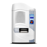
C: X center spacing. Dimension C specifies the horizontal distance
between well centers in millimeters. That is, the distance between wells A1,
A2, A3, and so on.
Example: For a 1536LDV DMSO plate type, C is 2.25 mm.
The valid range for C is 0.05 mm to 9.00 mm.
Refer to ANSI/SBS 4-2004 for more information.
D: Y center spacing: Dimension D specifies the vertical distance between
well centers in millimeters. That is, the distance between wells A1, B1, C1,
and so on.
Example: For a 1536LDV DMSO plate type, D is 2.25 mm.
The valid range for D is 0.05 mm to 9.00 mm.
Refer to ANSI/SBS 4-2004 for more information.
Figure 5.30 Plate dimensions E, F, G, and H.
E: Plate height: Dimension E specifies the overall height of the plate in
millimeters.
Example: For a 384PP_DMSO plate type, E is 14.4 mm.
Refer to ANSI/SBS 2-2004 for more information.
The valid range for E is 6.50 mm to 16 mm (higher plate height is not
included in ANSI/SBS standards).