Lake Shore Model 330 Autotuning Temperature Controller User’s Manual
Installation 2-3
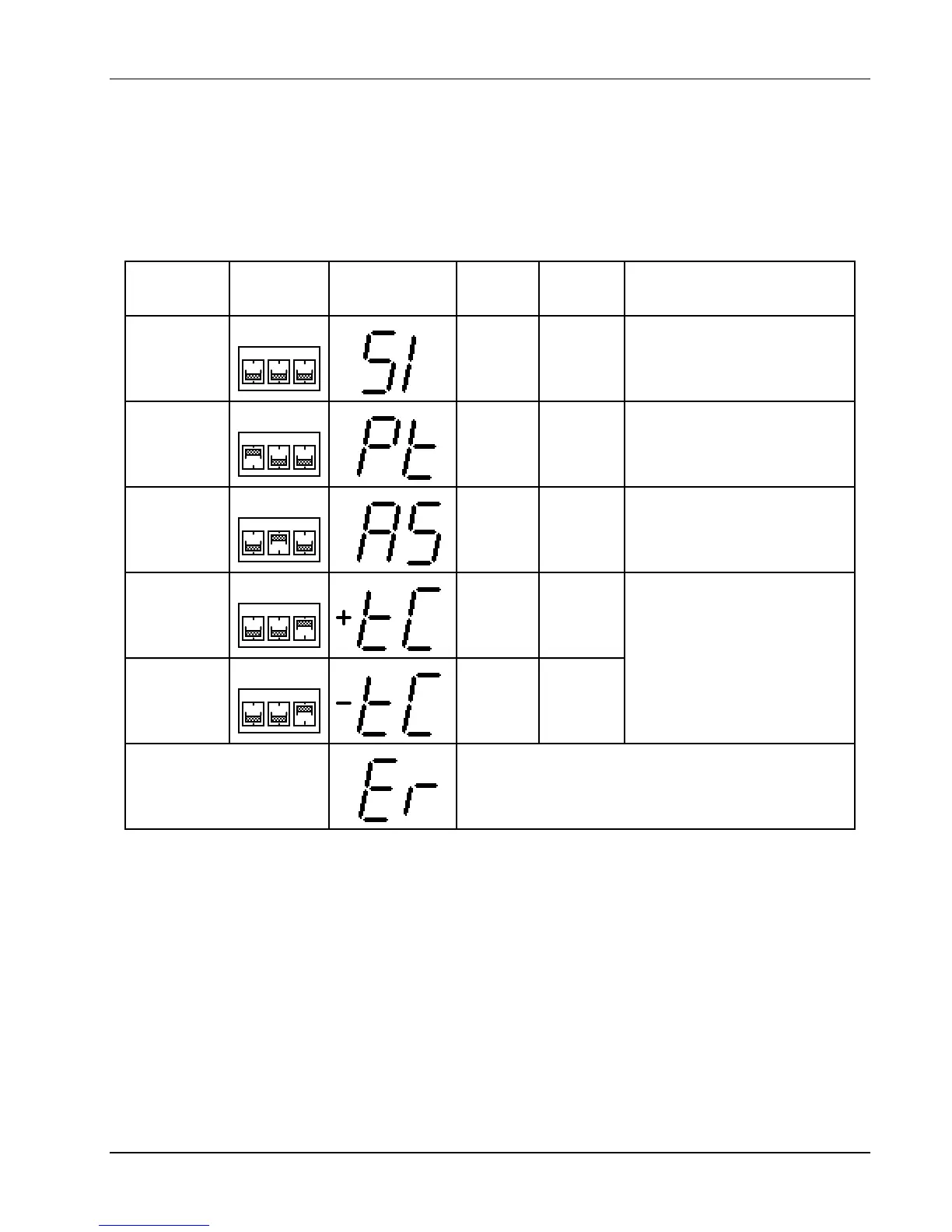
2.4 SENSOR INPUT SETTINGS
To configure sensor input type, set DIP switches S1 and S2 on the main PCB inside the unit. To check DIP
switch settings, press Input Type. Input configurations are shown in Table 2-1.
To change the DIP Switch settings, refer to Paragraph 5.9. Switch diodes and resistor sensors in the field with
no recalibration. Thermocouple sensors cannot be exchanged in the field, but compensation can be turned on
or off with the Input Type key.
Table 2-1. Sensor Input Setup
12
3
PT
AS
TC
SensorSensor
DIP SwitchDIP Switch
SettingsSettings
Display WhenDisplay When
Input TypeInput Type
Key is PressedKey is Pressed
SensorSensor
UnitsUnits
InputInput
RangeRange
StandardStandard
Curve(s)Curve(s)
Silicon Diode
(DT-400
Series)
Volts 0 to 2.5
2 Curve10
4 Curve 10 SoftCal
Thermocouple
(compensation
on)
Millivolts
15 to 15
12
3
PT
AS
TC
Platinum
RTD
Ohms 0 to 300 3 DIN Curve 43760
12
3
PT
AS
TC
GaAlAs
Diode
Volts 0 to 6.0 None
12
3
PT
AS
TC
10 to 10
6 AuFe 0.07% vs. Chromel
7 AuFe 0.03% vs. Chromel
8 Type E (chromel-constantan)
9 Type K (chromel-alumel)
10 Type T (copper-constantan)
12
3
PT
AS
TC
Thermocouple
(compensation
off)
Millivolts
*
*
DIP Switch S1 is for Channel A and S2 is for Channel B.
If the internal DIP switches are improperly set, the
display will read Er when the Input TypeInput Type key is
pressed. The normal front panel display will show
dashes - - - - to indicate improper DIP switch setting.
Improper Switch Setting
2.5 GROUNDING AND SHIELDING
To protect operating personnel, the National Electrical Manufacturer’s Association (NEMA) recommends, and
some local codes require grounded instrument panels and cabinets. This instrument comes with a three-
conductor power cable which grounds the instrument when plugged into an appropriate receptacle.
Grounding and shielding signal lines are major setup concerns. The Model 330 allows 4-wire measurement of
diode voltage and resistance. To prevent inaccuracy, isolate diode and resistive sensor leads from earth
ground. However, thermocouple sensors may be grounded. Shield sensor cables whenever possible. Attach
shields to the input connector shield pin. Do not attach the shield at the sensor end.
The heater output is isolated from earth ground. To prevent heater noise coupling into the measurement, do
not allow the heater output to contact earth ground. The rear panel earth ground (GND) is for shielding only.
Model 330 digital logic ties directly to earth ground for interface communications. Separate sensor lines and
digital communication lines whenever possible to prevent excess noise in the measurement.
 Loading...


