Lake Shore Model 330 Autotuning Temperature Controller User’s Manual
5-6 Service & Calibration
5.8 ERROR MESSAGES
On power up, the Model 330 checks internal memory. There are two potential error messages. The first error,
Er01, indicates an unsuccessful attempt to write and then read the internal non-volatile RAM. This error is not
user-correctable. Consult the factory.
The second error, Er02, indicates an unsuccessful attempt to read the internal non-volatile RAM for the Model
ID. Sometimes, initializing memory corrects this error. To initialize memory, press and hold both
Escape and
Units for about 20 seconds. Release when the power up sequence begins. Perform this operation only under
extreme circumstances; it erases any user-defined curves in memory.
There are two sensor input error messages. If an input signal from the sensor exceeding full scale is applied
to the input leads,
OL indicates the overload. If no signal or a wrong polarity signal exists at the input leads,
Er27 indicates a Zero Error for Channel A or Er28 for Channel B. The Model 330 displays dashes “- - - ” if the
input switches are improperly set.
Finally, Er30 appears if the measured heater output does not match the predicted output. The controller turns
the heater off. Check heater resistance, test for shorts in the heater wiring, then turn the heater on again. If the
error message returns, consult the factory.
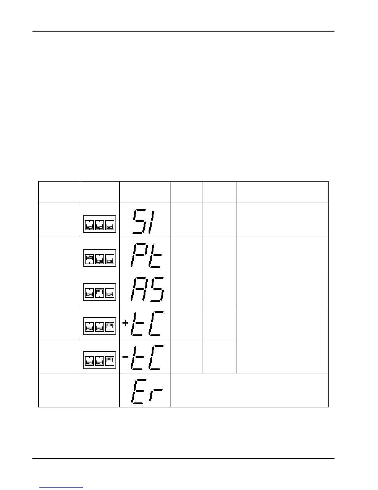
Table 5-1. Sensor Input Setup
12
3
PT
AS
TC
SensorSensor
DIP SwitchDIP Switch
SettingsSettings
Display WhenDisplay When
Input TypeInput Type
Key is PressedKey is Pressed
SensorSensor
UnitsUnits
InputInput
RangeRange
StandardStandard
Curve(s)Curve(s)
Silicon Diode
(DT-400
Series)
Volts 0 to 2.5
2 Curve10
4 Curve 10 SoftCal
Thermocouple
(compensation
on)
Millivolts
15 to 15
12
3
PT
AS
TC
Platinum
RTD
Ohms 0 to 300 3 DIN Curve 43760
12
3
PT
AS
TC
GaAlAs
Diode
Volts 0 to 6.0 None
12
3
PT
AS
TC
10 to 10
6 AuFe 0.07% vs. Chromel
7 AuFe 0.03% vs. Chromel
8 Type E (chromel-constantan)
9 Type K (chromel-alumel)
10 Type T (copper-constantan)
12
3
PT
AS
TC
Thermocouple
(compensation
off)
Millivolts
*
*
DIP Switch S1 is for Channel A and S2 is for Channel B.
If the internal DIP switches are improperly set, the
display will read Er when the Input TypeInput Type key is
pressed. The normal front panel display will show
dashes - - - - to indicate improper DIP switch setting.
Improper Switch Setting