Lake Shore Model 330 Autotuning Temperature Controller User’s Manual
Installation 2-9
2.9 HEATER SETUP
Model 330 heater output is on the rear panel as a Dual Banana Jack. A mating connector is
supplied. Current is driven from the Heater Output HI connection to the LO connection.
Connect a resistive load of 50 Ω for the 50 Watt heater setting or 25 Ω for the 25 Watt
heater setting between these two points.
The factory sets the Model 330 jumper per Customer request at the time of order, and
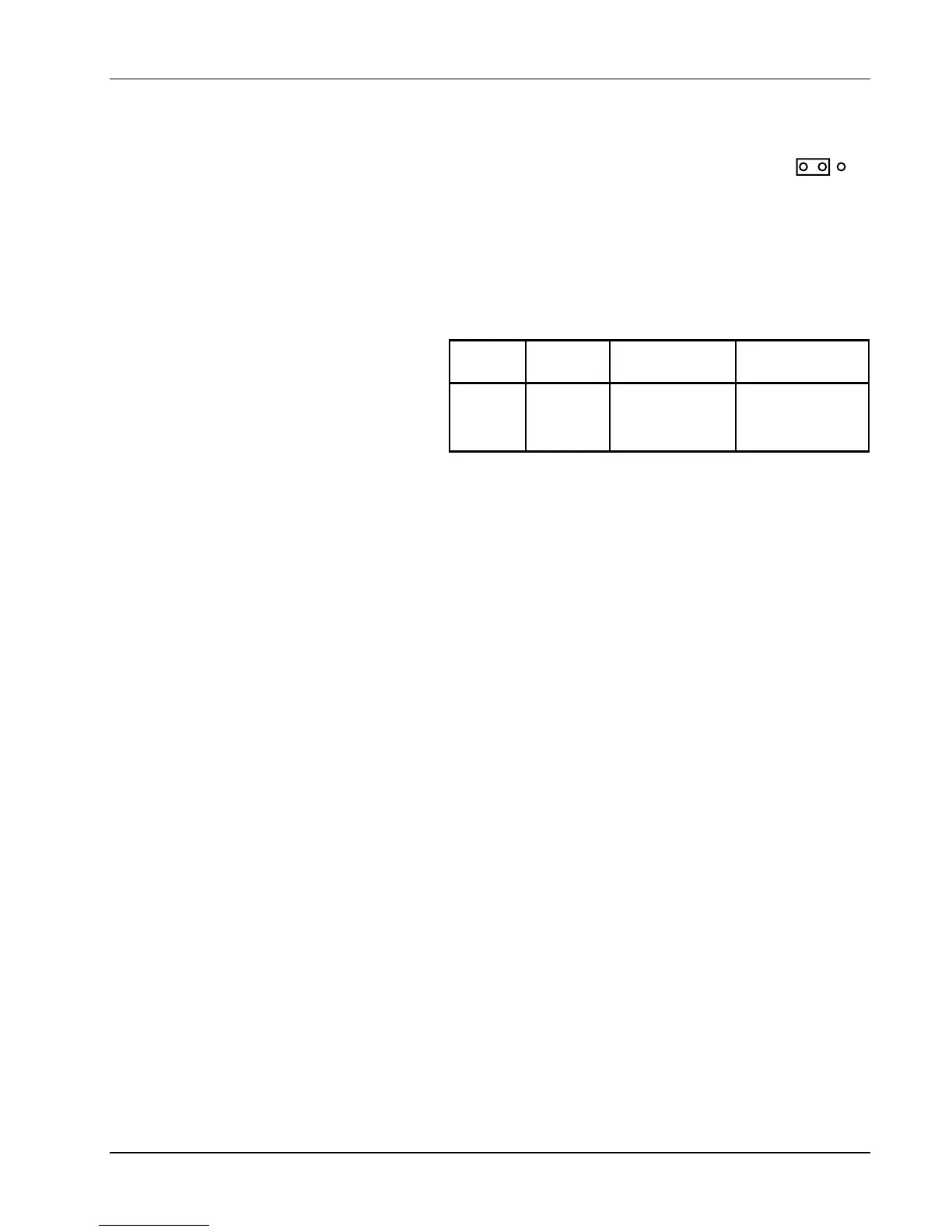
indicates the setting on the B Page inside the front cover. The jumper is set to 25 for 25 W
output or 50 for a 50 W output. To check the heater setting before first operation, see
Paragraph 5.7 for instructions on properly opening and closing the instrument, then look for
JMP9 (Figure 2-2) on the Model 330 Printed Circuit Board (Figure 5-9).
CAUTION: Do not change the Heater Jumper (JMP9) with the instrument power on.
The heater output is 1 A on High range, 0.3 A
on Medium, and 0.1 A on Low range, and
needs no fuse. The Model 330 powers either a
25 W or 50 W resistive heater for maximum
heater output. Larger resistance may be used,
but results in lower maximum power output.
For example, the output compliance voltage
for a 25 W heater setting is 25 volts, so a 100 Ω heater resistance would allow a maximum power output of
6.25 watts [(25V)
2
/100Ω].
If the heater load drops below 10 Ω for a 25 W heater setting, or 35 Ω for a 50 W heater setting, the output
turns off to prevent instrument overheating. If this occurs, cycle the heater range through OFF to re-engage
the heater.
NOTE: The heater output is isolated from earth ground. To prevent heater noise coupling into the
measurement, do not allow the heater output to contact earth ground. Within a cryostat, use 30 gauge
stranded copper lead wire (ND-30) to connect to the heater. Do not run heater leads coincident with the
sensor leads due to potential capacitive pick-up between the two sets of leads. If heater leads must be close
to sensor leads, twist them so they cross at 90 degrees.
Error 30 (Er30) appears if measured heater output does not match the predicted output, and the controller
turns the heater off. Check heater resistance and test for shorts in heater wiring, then turn the heater on again.
If the error message returns, consult the factory.
2.10 RACK MOUNTING
The Model 330 ships with plastic “feet,” ready for use as a bench instrument. As an option, the Model 330
installs in a standard 19 inch instrument rack. For information on the optional Model 3022 Half-Rack Mounting
Kit for a single controller, see Paragraph 6.3 and Figure 6-4. For information on the optional Model 3026 Dual
Mounting Shelf for side-by-side mounting of two controllers, see Paragraph 6.3 and Figure 6-5.
2.11 POWER UP
This paragraph covers the Power Up Sequence (Paragraph 2.11.1), Power Up (PUP) Configuration
(Paragraph 2.11.2), and Power Up Errors (Paragraph 2.11.3).
2.11.1 Power Up Sequence
1. All elements of the LED display (including Heater %) light.
2. The initials for Lake Shore Cryotronics, Inc. (LSCI) appear in the top window; the numbers 330 appear in
the bottom window.
3. The top line displays the IEEE-488 address (default 12); the bottom line displays the Serial interface Baud
rate (default 300).
4. The Sensor A input type displays in the top window (see Table 2-1), while the curve number displays in
the bottom window (see Table 2-3).
5. The Sensor B input type is displayed in the top window (same as displays in Table 2-1), while the curve
number is displayed in the bottom window (as defined in Table 2-3).
HEATER
25
50
JMP9
Figure 2-2
Heater Jumper
(JMP9)
Heater
Range
Heater
Current
25 W with 25 Ω
ΩΩ
Ω
Heater Power
50 W with 50 Ω
ΩΩ
Ω
Heater Power
HIGH
MEDIUM
LOW
0 to 1 A
0 to 0.3A
0 to 0.1 A
25 Watts
2.5 Watts
0.25 Watts
50 Watts
5 Watts
0.5 Watts


 To Next Page