Lake Shore Model 330 Autotuning Temperature Controller User’s Manual
5-2 Service & Calibration
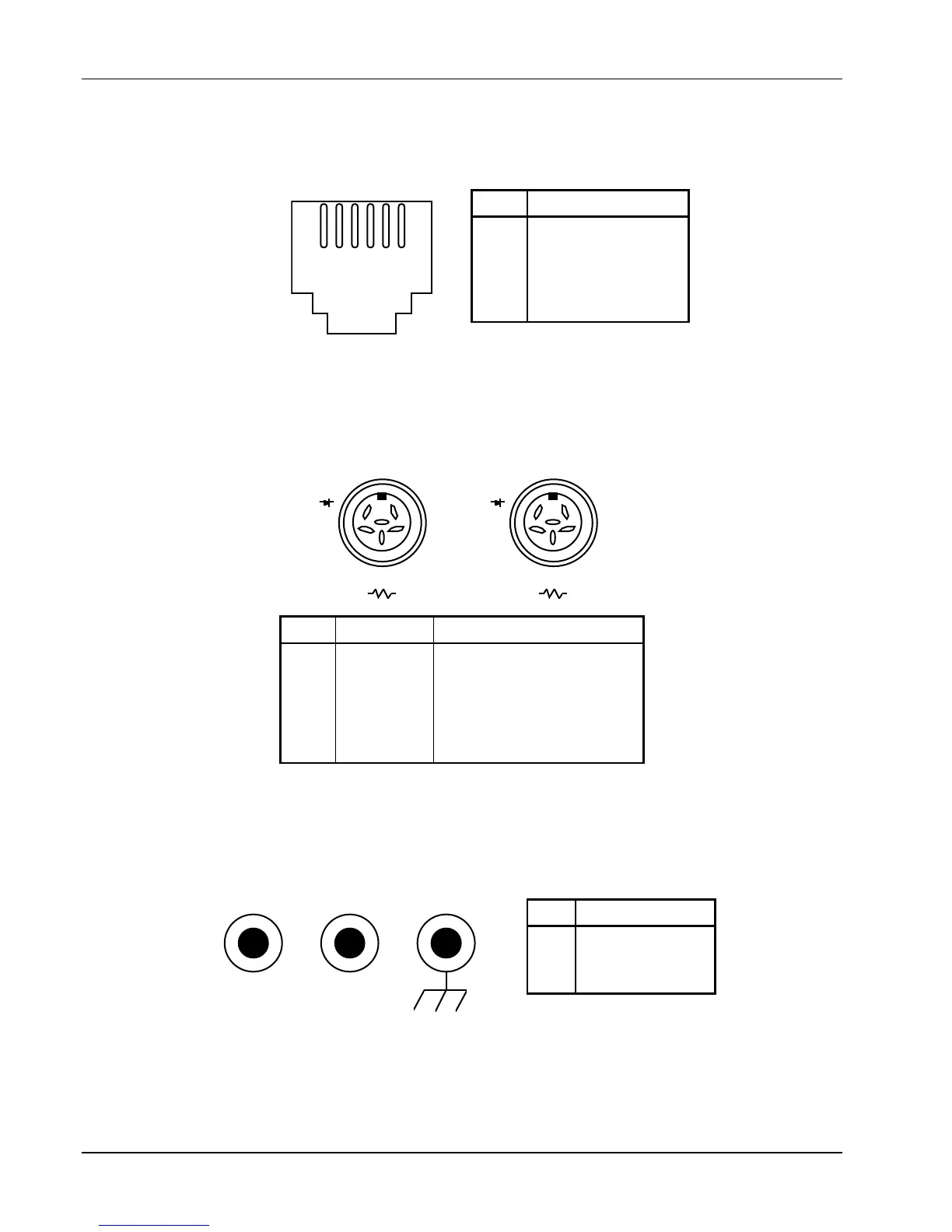
5.3 REAR PANEL CONNECTOR DEFINITIONS
Figures 5-2 thru 5-4 define Serial I/O, Analog Output, Sensor input, and Heater Output connectors.
Figure 5-2. SERIAL I/O RJ-11 Rear Panel Connector Details
I+
I–
V–V+
I+
CHANNEL A
CHANNEL
I+
I–
V–V+
I+
PIN Symbol DESCRIPTION
1
2
3
4
5
6
I–
V–
+I (resistor)
+V
+I (diode)
none
– Current
– Voltage
+ Current 1 mA (Platinum)
+ Voltage
+ Current 10 µA (Diodes)
Shield
Figure 5-3. Sensor CHANNEL A and B Rear Panel Connector Details
Figure 5-4. HEATER OUTPUT Rear Panel Connector Details
PIN DESCRIPTION
1
2
3
4
5
6
RS-232C In (RxD)
RS-232C In (RxD)
RS-232C Ground
RS-232C Ground
RS-232C Out (TxD)
RS-232C Out (TxD)
654321
SERIAL I/O
HEATER OUTPU
HI LO GND
PIN DESCRIPTION
1
2
3
HI
LO
GROUND

 Loading...


