11
General Information FMS Operating Principle
FMS Digital Inputs For the FMS to function according to the requirements of a combustion
system, the condition signals from the system must be relayed to the FMS.
These signals include:
Pre-ventilation suppression Air pressure monitor
Gas safety interlock circuit Gas pressure > min.
Oil safety interlock circuit Ignition flame
Boiler safety interlock circuit Burner on
Ignition position acknowledgement Fault reset
High firing rate acknowledgement Re-circulation On
Fuel selection Control release
Flame signal Set-point switch over
(only with integral load control unit)
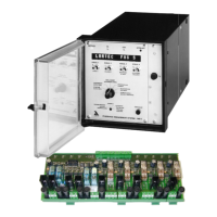
For use in burner control, the FMS emits 9 digital signals, which are
converted by relay module (type 6 60 R 0016) into twelve output signals
for 230 V:
Main gas 1 Ignition valve
Main gas 2 Ignition transformer
Oil Release ignition gas line
Heated oil distribution Fan
Oil operation signal Pre-ventilation / post-ventilation
Gas operation signal Fault signal
___________________________________________________________________
FMS operating sequence The operating sequence described relates to a usual configuration of the
(for diagram of example, unit. The various parameter settings can result in a somewhat different
see appendix) sequence.
___________________________________________________________________
A signal is first sent to terminal 2 (burner ON), indicating when the burner is
to start. The FMS then interrogates the safety interlock chain for the
selected fuel and the air pressure monitor contact. If the fuel is selected via
the fuel safety interlock circuits, the FMS performs a plausibility check. If it
does not detect a satisfactory condition, a corresponding text message is
emitted and the process control stops.
If all signals are OK, the fan output is activated and the ducts run to their
bottom stop as a check. The "pre-ventilation/post-ventilation” output is
activated. Once all ducts have reached their bottom stop, they open for
aeration. Any leakage test configured runs in parallel.
In the case of control elements, aeration is used to enter and to check the
range limits. The fuel control element, after reaching its top position, runs
back into the ignition position. All other ducts remain in the open position.
The FMS now interrogates the high firing rate acknowledgement and the air
pressure monitor. If these signals are OK, the parameterised aeration time
runs. If a duct is configured for re-circulation, this opens with a time delay.
On reaching the parameterised re-circulation delay time, the pre-ventilation
time stops. As soon as the re-circulation duct has reached the aeration
position, the aeration time continues. Once this time has elapsed the
ducts run into the programmed ignition position (re-circulation fully
closed). Once all ducts have reached ignition position, the FMS
interrogates the ignition position acknowledgement. In gas operation the
gas pressure monitors must also be in a satisfactory condition prior to
ignition.
The ignition transformer is now activated alone for the duration of the
pre-ignition time (transformer start-up time).

 Loading...