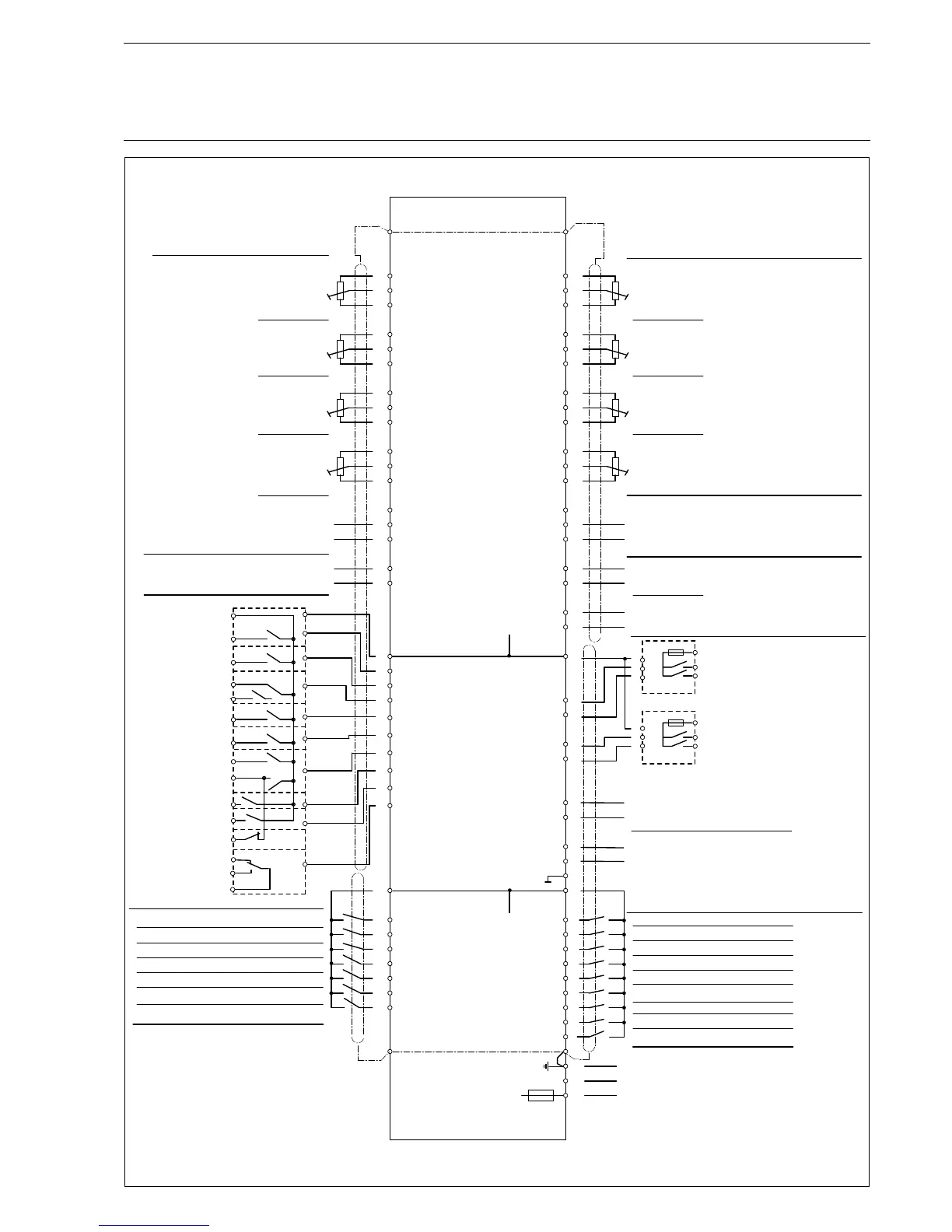
Appendix FMS 4 / FMS 5 Connection Diagram
two 2
FMS 5 Type 6 65 F 0030 with three and 2
FMS 4 Type 6 64 F 0030 with and continuous control three-point step control outputs
continuous control three-point step control outputs
140
9
24V DC
8
PE
N
L
F1
3m
1
5
A
T
35
33
-
+
34
29
+
27
67
12
13
14
15
45
18
17
19
20
21
23
25
32
30
+
-
68
65
63
66
11
47
49
69
70
46
44
42
52
50
48
58
56
54
64
62
60
10
31
75
5K
5K
5K
5K
5K
5K
9
72
43
41
36
76
71
+
-
+
-
5K
5K
16
10
73
74
81
82
83
87
84
85
86
88
93
94
89
91
92
90
7
6
5
4
3
2
1
28
22
24
26
55
53
51
61
59
57
95
68
41
36
76
45
16
11
67
43
10
+
+
-
-
-
1
2
3
5
6
4
60R13
1
2
3
5
6
4
60R13
24V DC
60R16
Channel 1
Channel 1
Channel 1
L 230V AC
0/4...20mA
0/4...20mA
Channel 1
Control element feedback
either potentiometer or
analog signal (current)
Channel 2
Channel 3
Channel 4
PE bus bar
Load message
either potentiometer
TPS or analog signal (current)
Load
Correction input 2
0/4...20mA
Correction input 1
Outputs
Channel 3 open
Channel 3 close
L - motor
Channel 4 open
Channel 4 close
L - motor
Channel 3 close
Channel 3 open
Channel 4 open
Channel 4 close
Channel 2
Earth
Neutral conductor
Phase 230V, 50/60 Hz
Signal inputs
Channel 1
Channel 4
Channel 3
Channel 2
Channel 5 feedback
or Channel 5 output
Redundante signal inputs
are needed only where
single signals are not
error-free
( only on FMS 5 )
Monitor output 4-20mA
(Flame intensity)
Maingas 1
Maingas 2
Oil distribution
Oil valves
Fan
Ignition valves
Ignition transformer
Pre-ventilation
Fault
Main gas 1
Main gas 2
Oil
Ignition valves
Ignition transformer
Fan
Fault
Oil-/gas operation
Pre-ventilation time ended
PE bus bar
Oil safety interlock circuit
Air pressure monitor
Gas pressure > min
external ignition position
acknowledgement
Fuel selection
open: oil, closed: gas
Ignition flame signal
Control release
Re-circulation "ON"
Fault unlock
Flame signal
Boiler safety interlock circuit
Gas safety interlock circuit
Pre-ventilation suppression
Burner On
Oil operation signal
Gas operation
signal
R
e ase pi
t
l
e lo
g
s
lin
e
a
External high firing rate acknowledgement
To be used only in a grounded power line network!