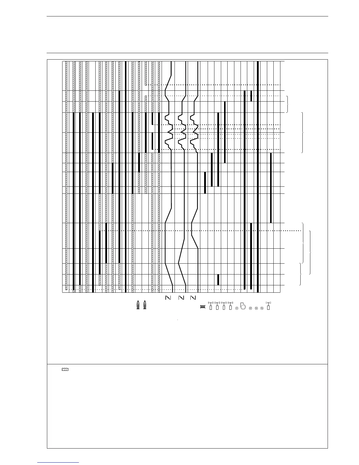
Appendix Process Sequence Chart
Gas operation with pilot burner, leakage test and Ignition flame monitor
nd
t9 2 safety period 3 sec.****
t10 Operating phase any
t11 Control mode any
t12 Time for pressure relief
in the gas test line 3 sec.
t13 Post-ventilation time 0-999 sec. adjustable
t14 Control elements at base load
t15 After-burning time 0-30 sec. adjustable
t16 Flame extinguishing check 5 sec.
t17 Leakage test, gas valve 2 30 sec.
*** Signal on terminal 1 clears the times t3, t4 and t5 at the end of t1 .
The leakage test, if integrated, runs although
**** For determination of the total safety periods according
to the standards, you have to add the reaction time of the
flame monitor to the time settings of the FMS (typ.1sec.).
M
1
35
5
69
2
73
71
72
75
8
7
7
4
6
74
86
85
82
83
84
88
89
92
90
93
91
87
Pre-ventilation suppression
Boiler safety interlock circuit
Gas safety interlock circuit
Oil safety interlock circuit
Burner On
Gas pressure > min.
Gas pressure < max.
High load acknowledgement
Ignition position acknowledge-
ment
Air pressure monitor
Fuel selection
Flame signal
Ignition flame
Control release
Re-circulation release
Air damper/fan
Fuel damper
Re-circulation damper/
Re-circulation fan
Ignition transformer
Ignition valve
Gas valve 1 (gas line)
Oil valves
Message oil operation
Fan On
Pre-ventilation/
post-ventilation
Message gas operation
Fault
external Ignition gas lead
heated oil distribution
Gas valve 2 (burner line)
*
**
***
Any condition
t1 Wait for Gas safety interlock circuit
air pressure monitor min. scan any
t2 Time for pressure build-up in the
gas test line 2 sec.
(only with leakage test activated)
t3 Servo drive running time
t4 Re-circulation damper delay 0-t5
t5 Aeration time 30-999 sec. adjustable
t6 Pre-ignition time 2-40 sec. adjustable
st
t7 1 safety period 4 sec.****
t8 Stabilisation period 3-10 sec. adjustable
* If output regulator in the unit is activated, this signal
is linked with the internal burner-start of this regulator
** If the re-circulation signal is absent, re-circulation valves remain
closed or run closed. (except at pre-ventilation)..
130
The function selection of the
terminal 7 is set by parameter 788.
If term.7 controls the ignition flame,
term.7 and term.8 are switched to
logical or between t6 to t9.
t
1
3
t
2
t t
4
5
t
t
3 6
t
7
t
8
t
9
t t
11 11
t t
12 13
t t
3
t
10
14
t t
14 14
t
t
17
t
1615
t
Version 4.0 8/99
x
x
x