FMS Fault Correction General Faults (A)
Aids
The FMS checks the function of all connected relays on the external modules.
Fault 500 520 921 The voltage present on the relay coils is read back.
501 521 922 Possible causes:
502 522 923 - Relay module not connected or connected wrongly
503 523 924 - Relay or relay module defective
504 524 925 - External voltage is fed into the corresponding terminal
505 525 926 - Terminal 9 and terminal 10 reversed
506 526 927 - 24V fuse F2 (front panel) defective
507 527 928 Check wiring
508 528 929 Check relay
- measure coil for continuity
With relay module V4:
- fuse F1-F4, F6 defective
- too less load at terminal 82-84
- at terminals 82-86 a testing current has to flow inboth directions. Otherwise
the relay module switches all outputs off during the selftest and the FMS
gets faulty.
- Impendance at a supply voltage of 230V # 100 kOhm
110V # 22 kOhm
As the case may be adequate loads have to be connected (e. g. ohmic
resistance or RC modue)
Outputs, which are not switched off by the FMS ( e. g. ignitionv valve at start
without pilot burner) doesn't need any load.
_____________________________________________________________________________________________________
The internal communication is not functioning.
Voltage off and back on
Fault 370 After changing EPROM
Check whether the monitoring program EPROM is correctly inserted
Otherwise:
Change processor card
_____________________________________________________________________________________________________
After changing a potentiometer the reference must be inputted again.
Fault 901 911 Voltage levels are checked in the unit. These can give rise to false errors
904 912 as a result of incorrect external wiring.
905 913 Check wiring
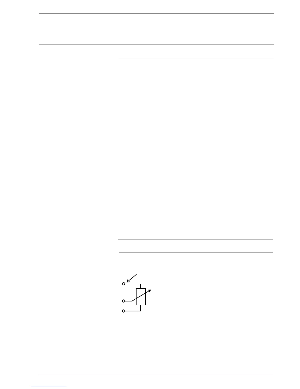
906 914 In the case of analog inputs the reference element serves for voltage supply
915 to the potentiometers.
+ External contact at connector
loop possibly transposed,
see D4 and E4
-
in the case of fault 904, 911 915, in particular, check the corresponding
reference, In the unloaded condition (terminal open) it is 2.4 V.
With potentiometer connected somewhat lower, depending on the resistance
of the potentiometer.
Re-enter reference value with potentiometer connected.
Selector switch (2) to "Setting"
Back to "Automatic"
- new reference value is stored.
93
A19
A20
A21
reference voltage