68
8 Options
8.5.2 LEDs
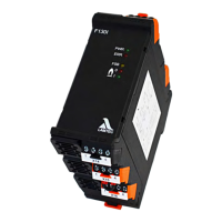
PBM100 has 4 LEDs which are connected as described below:
8.5.3 PROFIBUS DP Communication
Specification of the PB master input data
In the following, the input data that the PBM transfers to the master is specified:
LED Colour Description
PWR green ON: Module working in normal mode = fully initialised and
without any fault.
CAN green OFF: No communication or CAN BUS error
Blinking with 2 Hz: Errors (optional, if a CAN warning is
detectable)
ON: CAN is ready.
PB green OFF: no communication via PROFIBUS DP
ON: communication without error via PROFIBUS DP
ERR red OFF: no errors
ON: PBM100 Initialisation incomplete or not yet success-
fully completed or CAN message missing for more than 3 s.
Byte position
*
* Byte-number-wise from 1
Designation Configuration
1, 2 CO
e
actual value CO
e
display value,
uint 16 value in ppm
3, 4 CO
e
actual value status Measure value status (CO/O
2
)
and edge information (see the Bit encoding
CO/O2 actual value status in Chapter 8.5.4
Communication Appendix
5, 6 O
2
actual value O
2
display value,
uint16 value in [ppm], for status, see CO
e
7, 8 CO sensor voltage raw Electrode voltage 1,
int16 value in [1mV]
9, 10 O
2
sensor voltage raw Electrode voltage 2,
int16 value in [1mV]
11, 12 Probe voltage U
COe
Effective CO voltage,
int16 in [0.1mV]
13, 14 LT3 status Device status bit-encoded
15, 16 Warning word 1 LT warnings bit-encoded,
Bit [0 ... 15] for each warning 1 ... 16
17, 18 Warning word 2 LT warnings bit-encoded,
Bit [16 ... 31] for each warning 17 ... 32
19, 20 Fault word 1 LT faults bit-encoded,
Bit [0 ... 15] for each warning 1 ... 16
21, 22 Fault word 2 LT faults bit-encoded,
Bit [16 ... 31] for each warning 17 ... 32