HVM200 Reference Manual A-5
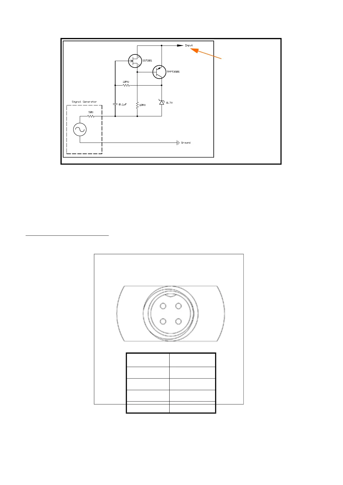
FIGURE A-2 Circuit for electrical testing
Circuit to Inject Electrical Signal into HVM200 ICP
®1
Inputs
Input
• Input type: ICP, IEPE, or CCP
• Excitation current: 2 mA
• Input connector: 1/4-28 4-pin male (the
input connection is also the transducer
connection)
• Measurement input voltage range: 1.8 to 16
Vdc
• Measurement AC reference bias voltage: 9
Vdc
• Absolute voltage range (min to max): 0 to
28 V
• Bandwidth: 0.4 Hz to 3000 Hz
• Range: Single range
• Sample rate: 7161.45833 Hz
FIGURE A-3 Pinout
Represents one
input for each axis
(x,y, z).
Refer to the
“Pinout” diagram
below for more
information on
the 1/4-28 input
connection.
1. ICP is a registered trademark of PCB Piezotronics,
Inc.
Pin Signal
A1 GND
A2 X Axis
B1 Y Axis
B2 Z Axis
A1
A2
B2 B1
 Loading...