EasyManua.ls Logo

Laski LS 160 User Manual

Laski LS 160
55 pages
To Next Page IconTo Next Page
Page #1 background imageLoading...
Page #1 background image
Orig. version 11.2016
OPERATING INSTRUCTIONS
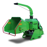
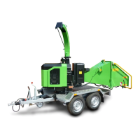
CHIPPER LS 160
model LS 160T

Questions and Answers:

Laski LS 160 Specifications

General IconGeneral
BrandLaski
ModelLS 160
CategoryChipper
LanguageEnglish

Summary

Operating Instructions

Chipper Model LS 160T

Front page title identifying the machine model and manufacturer.

Foreword

Product Introduction and Company Experience

Welcome message and overview of Laski's expertise in wood chippers.

Product Identification

Type Plate Details

Details found on the machine's type plate, including manufacturer and model designation.

Work Safety: Utilisation and Restrictions

Permitted Material and Usage

Defines the correct use of the chipper and the types of materials it can process safely.

Prohibited Uses and Conditions

Lists forbidden materials, circumstances, and locations for operating the chipper.

Work Safety: Operator Requirements

Operator Qualification and Training

Specifies age, capability, and training requirements for machine operators.

Safety Control Frame Operation

Explains the function of the safety frame and stop buttons for controlling loading rolls.

Work Safety: Machine Safeguards

Guard Integrity and Safety Elements

Emphasizes maintaining all safety guards and elements in good working order.

Safe Operating Environment

Guidance on machine stability, preventing unauthorized access, and discharge direction.

Work Safety: Operational Hazards

Ejected Particle and Cardan Shaft Safety

Warnings about ejected particles and safe handling of the cardan shaft during operation.

Tractor Coupling Safety Procedures

Instructions for safely coupling the chipper to the tractor, avoiding hazards.

Work Safety: Personal Protection

Required Personal Protective Equipment (PPE)

Lists essential PPE for operators, including helmets, gloves, and protective clothing.

General Operational Precautions

Covers advice on signals, material checks, and avoiding damage from objects.

General Operational Safety Warnings

Prohibited Actions and Conditions

Lists actions to avoid, such as operating with guards removed or in confined spaces.

Hot Parts and Moving Components Hazards

Warnings about touching hot machine parts and components during or after operation.

Transport on Public Roads

Road Transport Preparation Steps

Procedures for preparing the chipper for safe transport, including folding and securing parts.

Motor Vehicle Regulations for Transport

Tractor Coupling and Weight Limits

Guidelines for coupling the chipper to a tractor, considering weight and axle load.

Required Road Transport Equipment

Specifies required portable sets of lamps and reflectors for road transport.

Road Transport Specifications and Checks

Transport Position and Clearance Details

Details on transport position, clearance height, and speed considerations for road travel.

Pre-Transport Checks and Verification

Mandatory checks before road transport, including mud removal and lighting verification.

Work Safety Symbols Explained

Symbol Identification and Location

Introduces pictographs used on the machine and their corresponding locations.

Key Safety Symbol Meanings

Explains meanings of symbols for manual reference, maintenance, and coupling safety.

Safety Symbol Interpretation and Risks

Hazard Warnings and Pictographs

Details meanings of symbols for hot parts, running parts, ejected objects, and protective equipment.

Residual Risks: Oil Products

Information on the risks associated with hydraulic oil and its safe handling.

Health and Environmental Hazards

Exhaust Fumes and Hot Parts Warnings

Warnings about toxic exhaust fumes and the danger of touching hot machine components.

Personal Protective Equipment (PPE) Requirements

Lists mandatory PPE for operators and personnel within a 20-meter radius.

Operational Precautions and Design Features

Dust and Hazardous Brash Handling

Advice on managing dust and hazardous plant materials during operation.

Built-in Safety Design Features

Highlights protective guards and covers designed to prevent contact with moving parts.

Machine Controls and Safety Features

Switch Box and Ignition System

Details on the switch box, removable key, and signal lamps for machine activation.

Safety Frame and Loading Roll Control

Explains the safety frame's role in controlling loading rolls and additional control buttons.

Safety Mechanisms for Operation

Loading Roll Area Protection

Describes the hinged cover and terminal switch protecting the loading roll area.

Rotor Blocking Pin Function

Explains the safety pin used for blocking the chipping device rotor during maintenance.

Control System Details

Terminal Switch and Emergency STOP

Information on terminal switches for chute tilt and the function of the emergency STOP button.

Ignition Box and Running Hours Counter

Details on the ignition box for control and the 'S' key for managing running hours.

Loading Roll Control and Speed Regulation

Safety Frame for Loading Rolls

Describes the safety frame's operation for loading roll control and emergency stop functions.

Loading Speed Adjustment Mechanism

Explanation of the actuator used to regulate loading roll speed within a specific range.

Machine Usage and Preparation

Storage Guidelines for Chipper

Instructions for storing the chipper to protect it from weather and maintain its condition.

Pre-Operation Checks and Inspections

Essential checks before initial operation, including damages, bolted joints, and safety labels.

Maintenance and Tractor Coupling

Blade and Belt Maintenance Procedures

Guidance on checking and replacing blades, belts, and hydraulic oil filters.

Tractor Coupling Requirements

Specifies the tractor requirements for coupling, including hitch type and PTO shaft.

Tractor Coupling Procedures

PTO Speed and Hitch Attachment

Importance of matching PTO speed and details on attaching the machine to the tractor hitch.

Hitch Height Adjustment Mechanism

Explanation of how to adjust the machine's height using the hinge pin.

Cardan Shaft Adjustment Procedure

Shaft Length and Overlap Verification

Procedures for checking cardan shaft length, overlap, and safety splines for proper fit.

Shaft Retraction and Angle Limits

Guidance on maximum retraction and permissible angles to prevent shaft damage.

Putting the Chipper into Operation

Pre-Start Checks and System Activation

Ensures the chute and duct are clear, safety frame is set, and the NOSTRESS unit is activated.

Starting Procedure and Safety Steps

Steps to start the PTO shaft, engage the chipping wheel, and follow safety protocols.

Operation and Safety Controls

Loading Rolls Activation and Control

Instructions for starting and stopping the loading rolls using control buttons and the safety frame.

Safety Frame Adjustment for Emergency Stop

Ensures the safety frame is adjusted correctly for emergency stop activation.

Chipping Process Guidelines

Safe Chipping Conditions and Environment

Covers operating in suitable spaces, using the cardan shaft guard, and setting the discharge duct.

Material Loading and Chip Ejection

Advice on material loading, chip gathering, and safe discharge into containers.

Chipping Safety and Material Handling

Material Loading Restrictions and Practices

Details on prohibited materials, dimensions, and safe loading practices.

Work Area Observation and Stops

Emphasizes observing the work area and initiating immediate stops for safety.

Chipping Recommendations for Performance

Optimizing Chipping Efficiency

Tips for efficient chipping, blade maintenance, and avoiding overloading.

NOSTRESS System for Overload Protection

Guidance on using the speed regulation system to prevent overloading and manage material feed.

Stopping and Emergency Procedures

Putting the Chipper Out of Operation

Steps to safely stop the chipper, including waiting for run-out and turning off the PTO.

Emergency Situation Response Actions

Immediate actions required for emergencies like approaching persons, breakages, or strange noises.

Technical Description: Chipping Device

Loading Chute Design and Safety Frame

Details the construction of the loading chute, its safety frame, and its control function.

Technical Description: Machine Components

Loading Rolls and Chipping Wheel

Explains the function of loading rolls and the design of the chipping wheel.

Discharge Duct and Frame Structure

Describes the discharge duct for chips and the machine's frame structure.

Technical Parameters and Maintenance Overview

Machine Specifications Summary

Comprehensive list of machine parameters including dimensions, weight, and drive details.

Servicing by Authorized Personnel Only

Stresses that all servicing must be performed by authorized and qualified personnel.

Maintenance: Lubrication Procedures

Lubrication Points and Intervals

Details specific lubrication points and recommended intervals for bearings and guides.

Maintenance: Blade Grinding

Blade Regrinding for Optimal Geometry

Instructions for regrinding blades to maintain optimal geometry and balance.

Blade Edge Geometry Specification

Illustrates the detailed geometry required for proper blade edge grinding.

Maintenance: Chipping Adjustment

Clearance Setting for Quality Chipping

Explains how to set the clearance between blades and cutting edge for quality chipping.

NOSTRESS System: Speed Regulation

System Overview and Control Unit Functions

Describes the system's purpose for overload protection and the control unit's display functions.

Speed Regulation for Overload Protection

Explains how the system reduces material feed during overloading based on material type.

NOSTRESS System: Speed Sensor

Speed Sensor Setup and Verification

Details the speed sensor's placement, distance, and the LED indicator for proper sensing.

NOSTRESS System Protection Against Overvoltage

Overvoltage Protection Components

Explains how fuses and TVS diodes protect the electronics from voltage spikes.

V-belt Tension Adjustment Procedures

Belt Tensioning and Guard Replacement

Guidance on checking and adjusting V-belt tension and replacing belt guards.

Belt Slack and Drive Adjustments

Belt Slack Values and Tightening Methods

Provides recommended belt slack and finger pressure values and tightening procedures.

Hydraulic System Maintenance

Hydraulic Pump Drive Belt Adjustment

Instructions for adjusting the hydraulic pump drive belts and replacing belt guards.

Hydraulic Oil Filter Change Procedure

Details on changing the oil filter element and filling the hydraulic oil tank.

Maintenance Intervals Schedule

Electrical Installation Checks

Ensures wires are protected from oil and connections are clean for safety.

Hydraulic Oil and Filter Change Intervals

Specifies intervals for hydraulic oil and filter changes, recommending simultaneous replacement.

Checking and Oil Exchange Schedule

Hydraulic Oil Exchange Intervals

Table detailing hydraulic oil exchange intervals based on operating hours and conditions.

Failures and Troubleshooting Guide

Chipping and Loading Issue Resolution

Addresses common failures like blunt blades, worn edges, and loading roll malfunctions.

Troubleshooting Common Malfunctions

Loading Roll and NOSTRESS System Faults

Covers issues with loading rolls not turning, NOSTRESS system faults, and clogged discharge ducts.

Troubleshooting Bearing Issues and Waste Disposal

Bearing Overheating and Wear Solutions

Addresses overheating, lubrication, and wear issues with bearings.

Waste Disposal and Environmental Protection

Guidelines for disposing of waste materials and protecting the environment.

Warranty Information and Coverage

Manufacturer's Warranty Terms

Details the warranty period, what is covered, and exclusions based on usage.

Service Report and Maintenance Log

Maintenance Operations Record

Provides a template for recording maintenance operations and scheduling future service.

Hydraulic Scheme Diagram

Hydraulic Circuit Components and Flow

Diagram illustrating the hydraulic circuit, showing components and flow paths.

Electrical Wiring Diagram

Main Electrical Connections Overview

Shows the main electrical connections, relays, fuses, and wiring harnesses for the machine.

Electrical Schematics and Component Wiring

Sensor and Switch Wiring Details

Illustrates specific wiring for sensors, switches, and actuators, including connector pinouts.

Related product manuals