2.4.6 SPEAKERS LINES
(a) SPARE CHANNELS INPUT
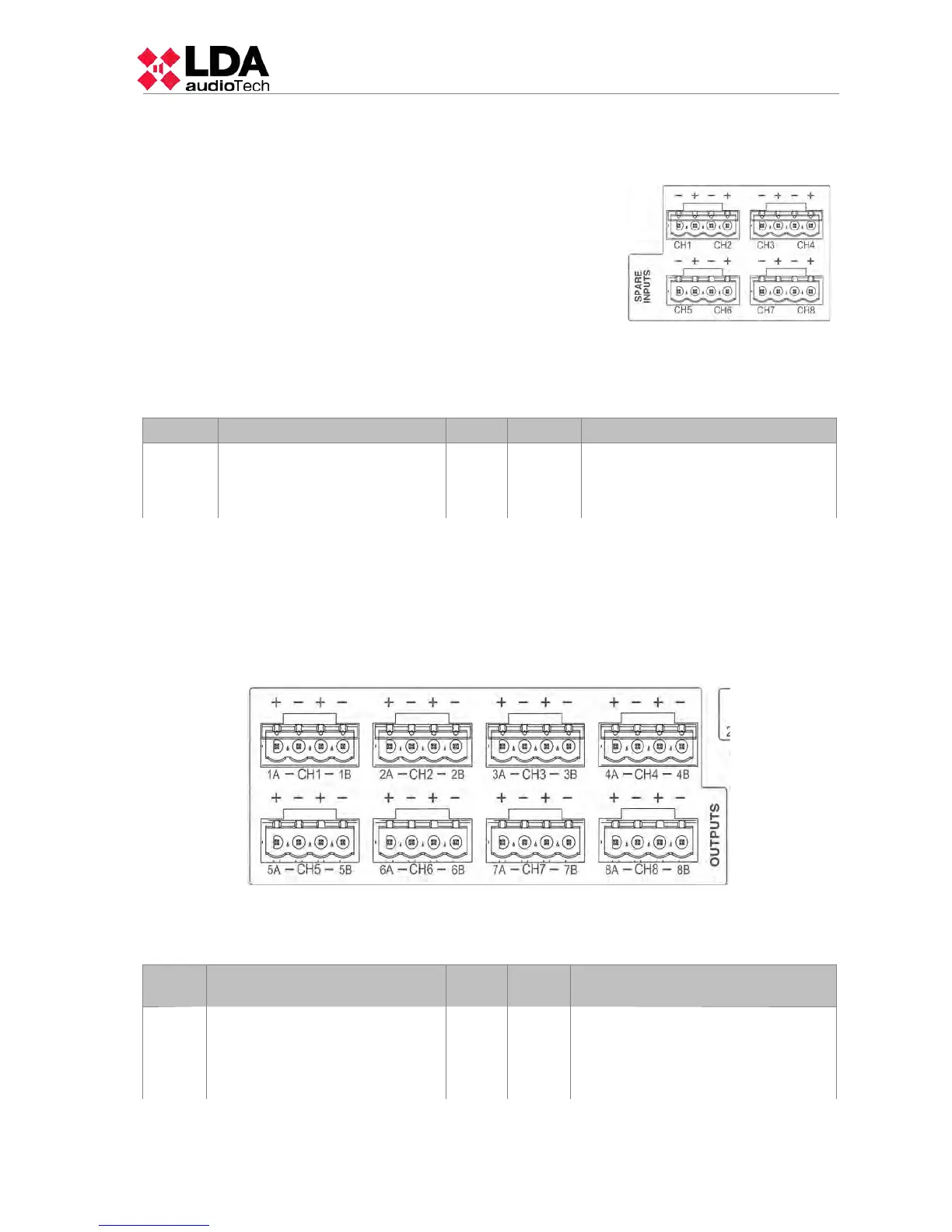
The equipment has 8 inputs back-up amplifier
channels per each internal amplifier. Each connection has
two terminals + and – where the redundant amplifier output
will be connected. The redundant amplifier must be a 100V
line public address amplifier with a minimum power equal to
the nominal channel amplification power of the equipment.
For more information about the connection of back-up
amplifier, see chapter 4.5 .
The connection is made with a 2-pin female euroblock
connector and pitch 5.08 mm (supplied with the unit). The
wire size range for each pole of this connector is: 0.5 2.5
mm2 (22 12 AWG).
Marking Description Type Signal Activation
SPARE
CH
INPUTS
X
Input amplification channel
corresponding to the channel
reservation amplification
equipment X
Input
+ -
NA
Table 12: Spare Channel Inputs
(b) SPEAKER LINE OUTPUT
The equipment has between 4 and 8 amplification channels, each channel has two
speaker line outputs marked as A and B. The rated power of the amplifier channel is divided
between both output lines. For more information about the connection of the speaker lines see
chapter 4.4 . Each line connection has two + and - terminals for connecting speakers to 100V
or low-impedance depending on the model.
The connection is made by euroblock female connector and 2-pin pitch 5.08 mm
(supplied with the unit). The wire size range for each pole of this connector is: 0,5 2,5 mm2
(22 12 AWG).
Marki
ng
Description Type Signals Activation
CHX
XA
XB
CHX Amplification channel X.
XA Speakers line A of amplification
channel X.
XB Speakers line B of amplification
channel X.
Output
+ -
NA
Table 13: Speaker Lines Outputs
LDA Audio Tech - Severo Ochoa Nº 31- 29590 MÁLAGA, ESPAÑA. Tlf: +34 952028805
15