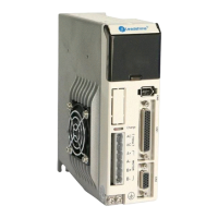
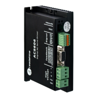
DatasheetoftheEasyServoDriveES2‐DA808
LeadshineTe c hnol ogy Co.,Ltd
11/F,BlockA3,iPark,No.1001XueyuanBlvd.Shenzhen,China Tel:1‐949‐608‐7270Fax:1‐949‐608‐7298
Web:www.leadshine.com Email:tech@leadshine.com
3 PUL+ I
Pulse signal: In single pulse (pulse/direction) mode, this input represents pulse signal,
each rising or falling edge active (software configurable); In double pulse mode
(software configurable), this input represents clockwise (CW) pulse, active both at high
level and low level. 5-24V when PUL-HIGH, 0-0.5V when PUL-LOW. For reliable
response, pulse width should be longer than 2.5uS(200K bandwidth) or 1uS(500K
bandwidth)
4 PUL- I
5 DIR+ I
Direction Signal: In single-pulse mode, this signal has low/high voltage levels,
representing two directions of motor rotation. In double-pulse mode (software
configurable), this signal is counter-clock (CCW) pulse, active both at high level and low
level. For reliable motion response, DIR signal should be ahead of PUL signal by 5μs at
least. 5-24V when DIR-HIGH, 0-0.5V when DIR-LOW. The direction signal’s polarity is
software configurable.
6 DIR- I
7 ALM+ O
Alarm Signal: OC (Open Collector) output signal, activated when one of the following
protection is activated: over-voltage, over current, braking error and position following
error. They can sink or source MAX 100mA current at 5V. The active impedance of
alarm signal is software configurable.
8 ALM- O
9 Pend+ O
In-position Signal: OC output signal, active when the difference between the actual
position and the command position is zero. This port can sink or source 20mA current at
24V. The resistance between Pend+ and Pend- is active at high impedance.
The signal also can be used for brake output by setting parameter NO 30004 in
ProTuner.
10 Pend- O
11 ENA+ O
Enable signal: This signal is used for enabling/disabling the driver. By default, high level
(NPN control signal) for enabling the driver and low level for disabling the driver. It is
usually left UNCONNECTED (ENABLED). Please note that the PNP and Differential
control signals are on the contrary, namely Low level for enabling. The active level of
ENA signal is software configurable.
12 ENA- O
13-22 NC -
No connection.
23 AO+ O
Encoder A + output
24 AO- O
Encoder A - output
25 BO+ O
Encoder B+ output
26 BO- O
Encoder B- output
27 ZO+ O
Encoder Z+ output
28 ZO- O
Encoder Z- output
29-44 NC -
No connection.
FG -
Ground Terminal for shield
3.2 Encoder Signal Input CN2
CN2 – Feedback Signal (Encoder) Connector
HDD15, 15Pin, Female
Pin Name I/O Description