DatasheetoftheEasyServoDriveES2‐DA808
LeadshineTe c hnol ogy Co.,Ltd
11/F,BlockA3,iPark,No.1001XueyuanBlvd.Shenzhen,China Tel:1‐949‐608‐7270Fax:1‐949‐608‐7298
Web:www.leadshine.com Email:tech@leadshine.com
Wiring Notes
In order to improve anti-interference performance of the drive, it is recommended to use twisted
pair shield cable.
To prevent noise incurred in PUL/DIR signal, pulse/direction signal wires and motor wires should
not be tied up together. It is better to separate them by at least 10 cm, otherwise the disturbing
signals generated by motor will easily disturb pulse direction signals, causing motor position
error, system instability and other failures.
If a power supply serves several drives, separately connecting the drives is recommended instead
of daisy-chaining.
It is prohibited to pull and plug power connector while the drive is powered ON, because there is
high current flowing through motor coils (even when motor is at standstill). Pulling or plugging
power connector with power on will cause extremely high back-EMF voltage surge, which may
damage the drive.
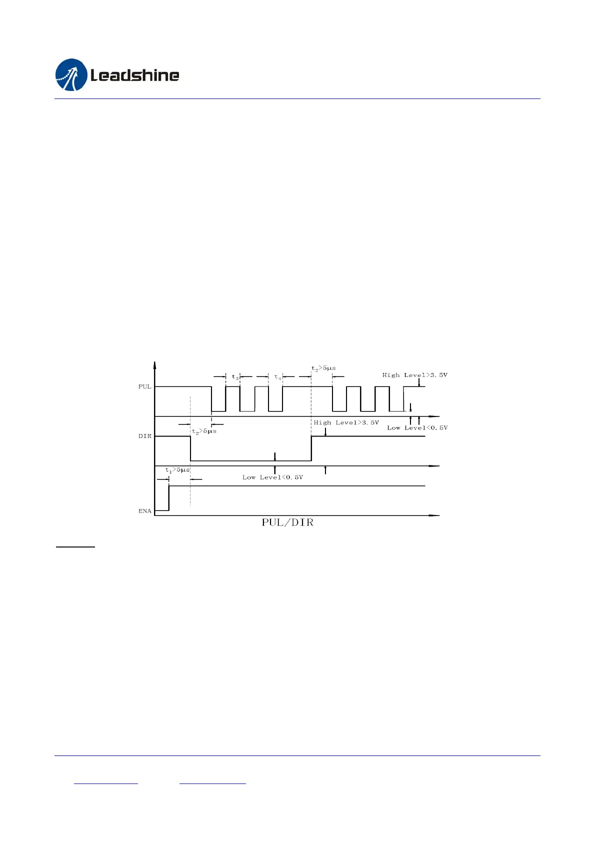
4.2 Sequence Chart of Control Signals
In order to avoid some fault operations and deviations, PUL, DIR and ENA should abide by some rules, shown as
following diagram:
Remark:
a) t1: ENA must be ahead of DIR by at least 5s. Usually, ENA+ and ENA- are NC (not connected). See
“Connector P1 Configurations” for more information.
b) t2: DIR must be ahead of PUL effective edge by 5s to ensure correct direction;
c) t3: Pulse width not less than 2.5s;
d) t4: Low level width not less than 2.5s.
4.3 Configuring ES2-DA808
4.3.1 Configuring ES2-DA808 by the on-board HMI
Users can configure the drive via the on-board HMI in the front panel. This HMI includes six
7-segment digits and five keys for users operation as follows: