B–2
Appendix B
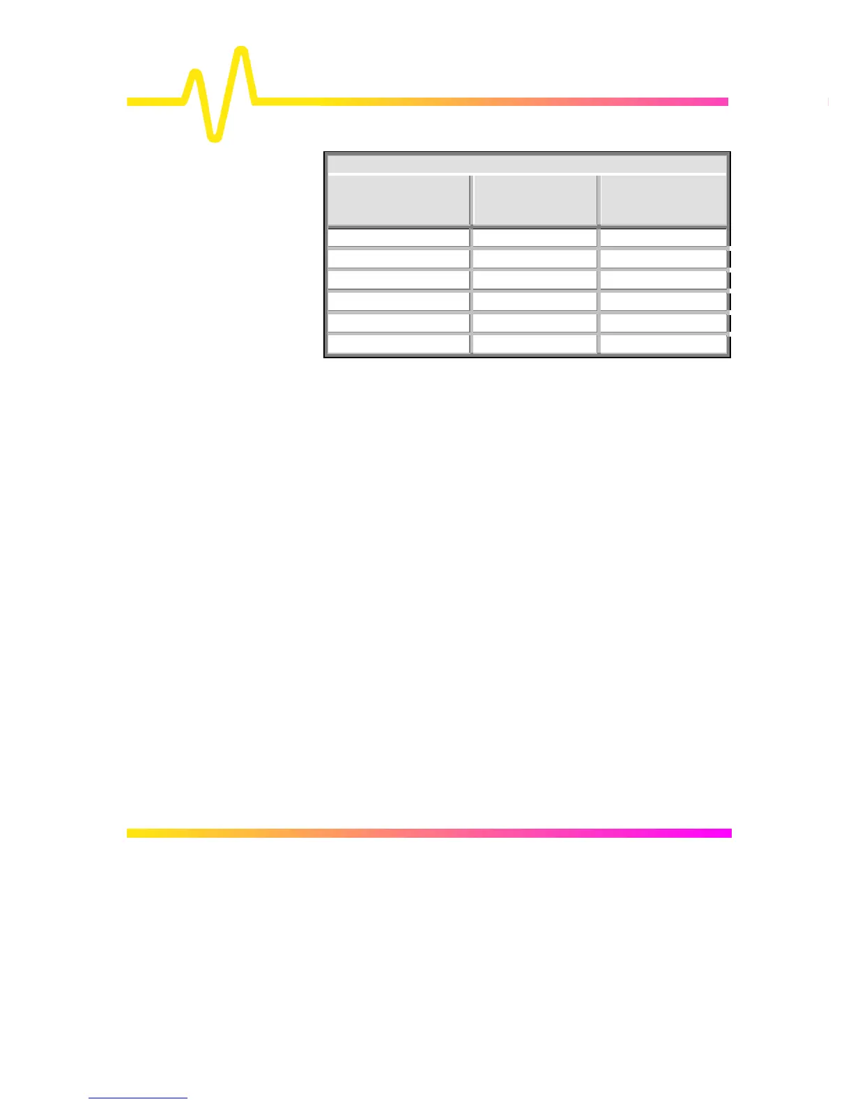
FIR Enhanced-Resolution-Filter Parameters
Resolution Increase
(Enhancement)
–3 dB Bandwidth
(× Nyquist)
Filter Length
(Samples)
0.5 0.5 2
1.0 0.241 5
1.5 0.121 10
2.0 0.058 24
2.5 0.029 51
3.0 0.016 117
With low-pass filters, the actual SNR increase obtained in any
particular situation depends on the power spectral density of the
noise on the signal. The improvement in SNR corresponds to
the improvement in resolution if the noise in the signal is white
— that is, if it is evenly distributed across the frequency
spectrum. If the noise power is biased towards high frequencies,
the SNR improvement will be better than the resolution
improvement. Whereas the opposite may be true if the noise is
mostly at lower frequencies.
SNR improvement due to the removal of coherent noise signals
—feed-through of clock signals, for example — is decided by
the fall of the dominant frequency components of the signal in
the passband. This is easily ascertained using Spectral Analysis.
The filters have a precisely constant zero phase response. This
has two desirable properties. First, the filters do not distort the
relative position of different events in the waveform, even if the
events’ frequency content is different. And second, because the
waveforms are stored, the delay normally associated with
filtering (between the input and output waveforms) can be
exactly compensated during the computation of the filtered
waveform.
All the filters have been given exact unity gain at low frequency.
Enhanced resolution should thus not cause overflow if the
source data is not overflowed. If part of the source trace were to
overflow, filtering would be allowed, but the results in the vicinity

 Loading...


