19
Attention!
Do not loosen the screws (10.1) below the
stage on the transmitted-light illumination
carrier because this would displace the
optical axis.
• Unscrew the screws (11.1) with a 3 mm fixed
spanner and remove the screws.
• Rotate the stage with the transmitted-light
illumination unit by 180°.
• Position the stage with the transmitted-light
illumination unit. The stage should lock in the
guide pins (10.2) on the microscope.
• Insert the screws (12.1) and tighten them.
• Mount the connecting cable in the plastic
guide below the stage (10.3).
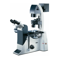
Fig. 10
1 Clamping screws for optical exis, 2 Guide pins, 3 Plastic
guide
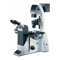
Fig. 11
1 Screws for repositioning the transmitted-light illumination
carrier
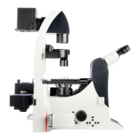
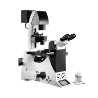
Fig. 12
1 Screws for repositioning the transmitted-light illumination
carrier, 2 Connecting cable
1
1
1
3
1
2
1
2
1
2
1
1


 To Next Page