18
Positioning the transmitted-light
illumination carrier
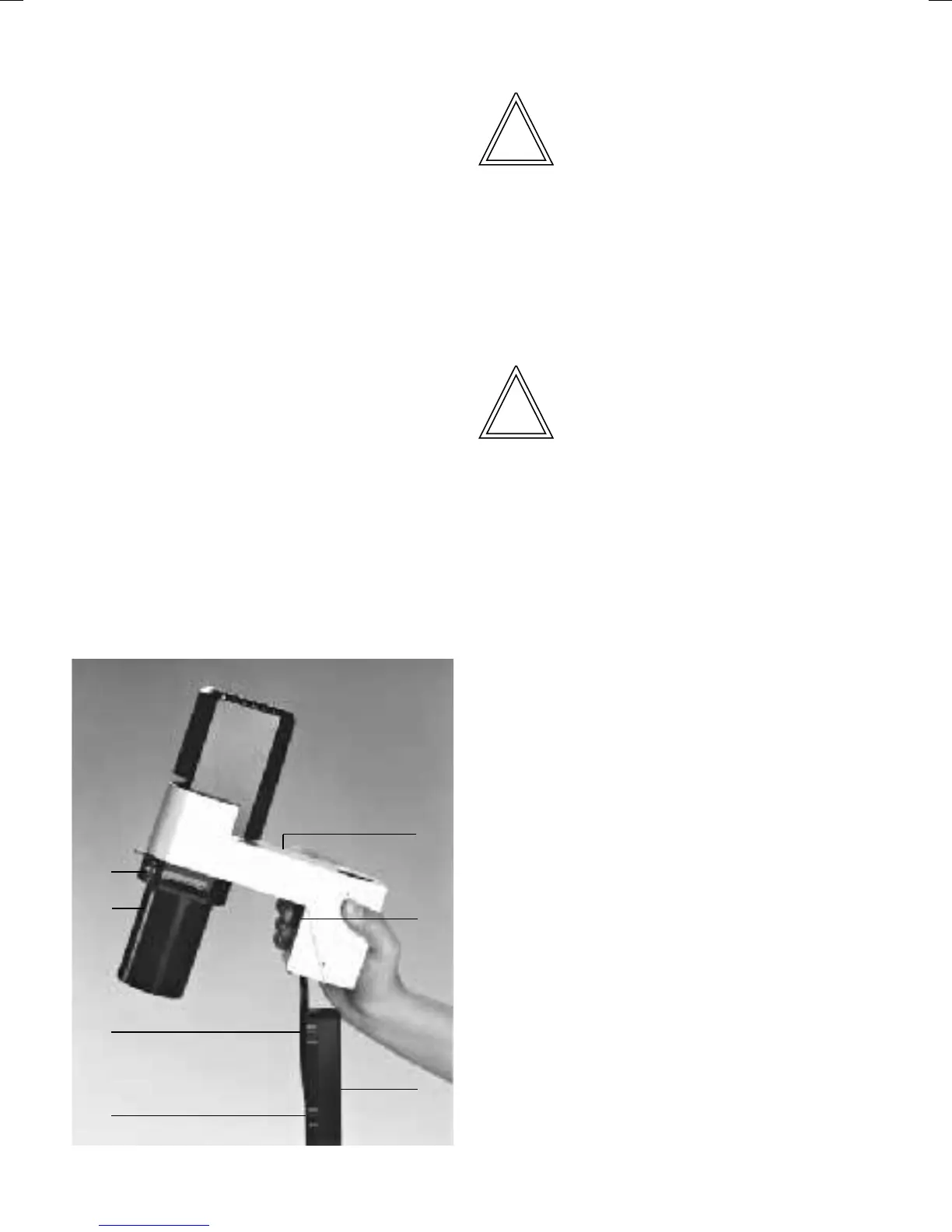
• Position the transmitted-light illumination car-
rier into the column from above while
pressing on the notched lever for the con-
denser level adjustment (9.5).
• Position the transmitted-light illumination
carrier (9.3) on the transmitted-light illumination
column (9.4) depending on the condensor used
(S 55 or S 90) and release the notched lever.
The markings (9.6) are referred to a liquid
level of 15 mm. For microscopes with dual
markings, the lower line indicates a liquid
level of 15 mm and the upper line indicates a
liquid level of 50 mm.
• Make sure that the transmitted-light illumi-
nation carrier is locked in place.
Fig. 9 Transmitted-light illumination unit with condenser
1 Condenser (S 90), 2 Condenser holder, 3 Transmitted-light
illumination carrier, 4 Transmitted-light illumination column,
5 Notched lever for condenser level adjustment, 6 Markings
Note
A screw (6.1) on the transmitted-light illumi-
nation column prevents that the condensor
collides with the specimen stage.
Repositioning the transmitted-light illumination
carrier with the specimen stage
Note
For the heating stage* only one position of the
transmitted-light illumination carrier is possible.
This position is determined by the existing holes
in the stage.
Repositioning of the transmitted-light illumina-
tion carrier is only possible with the DM ILB or
DMILT tubes.
The specimen stage can be made accessible
from three sides by repositioning it by 180°.
1
3
4
2
5
6
6


 To Next Page