Version 2.1
09/2010
NOVOLAS Basic AT
Interfaces 21
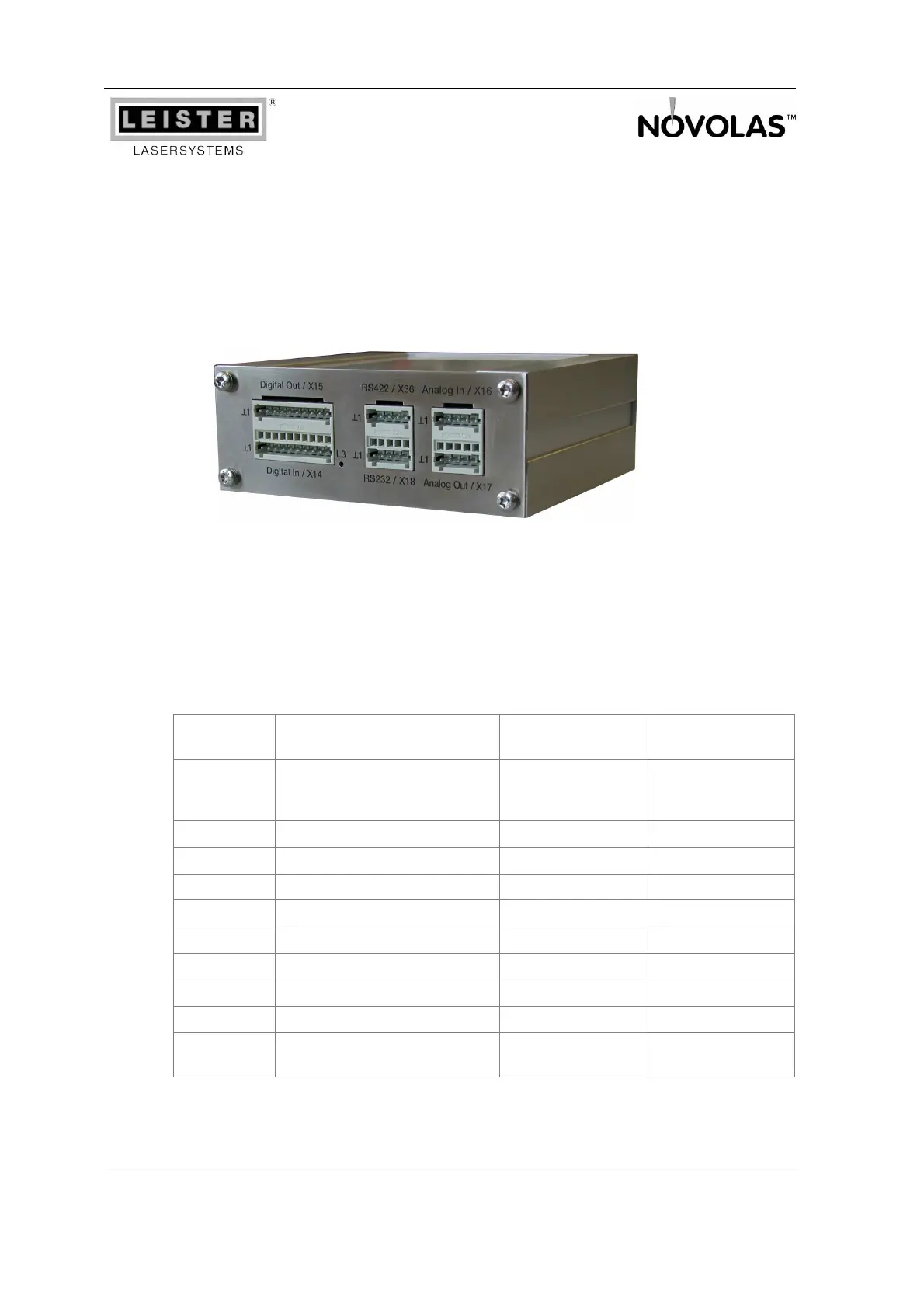
4.3 Customer I/O
This module is used to build the interface to the surrounding customer system (e.g.
PLC). It provides inputs to set the current and to switch the laser current on and off. It
signals the state of the system and the actually flowing laser current.
In systems with 3 and 4 laser units two Customer I/O are installed. The “lower”
Customer I/O (#A) controls laser units #A and #B and the “top” Customer I/O (#B) controls
laser unit #C and #D.
4.3.1 Digital Inputs (X14)
The digital inputs are DC-isolated. The reference potential needs to be supplied by
the customer on terminal 14.1. Voltages higher than 14V are considered logic high.
Terminal Description Potential
Trigger-Info
DataManager
X14.1 External digital IO supply and
signal GND, connected to
X15.1
Reference potential
X14.2 Aiming laser off +24V = lasers off Bit 7
X14.3 res. / not used Bit 6
X14.4 res. / not used Bit 5
X14.5 res. / not used Bit 4
X14.6 Trigger laser unit #B (#D) +24V = active Bit 3
X14.7 Gate laser unit #B (#D) +24V = active Bit 2
X14.8 Trigger laser unit #A (#C) +24V = active Bit 1
X14.9 Gate laser unit#A (#C) +24V = active Bit 0
X14.10 External digital IO supply,
connected to X15.10
+24V
The functionality of the gate and trigger input depend on the system's configuration
which can be reprogrammed by software (see chapter 6).
Figure 7: Interfaces on the Customer I/O, Rear View