Screw specifications Number of screws
M2.0 x 3
8 (for UMA) / 10 (for DIS)
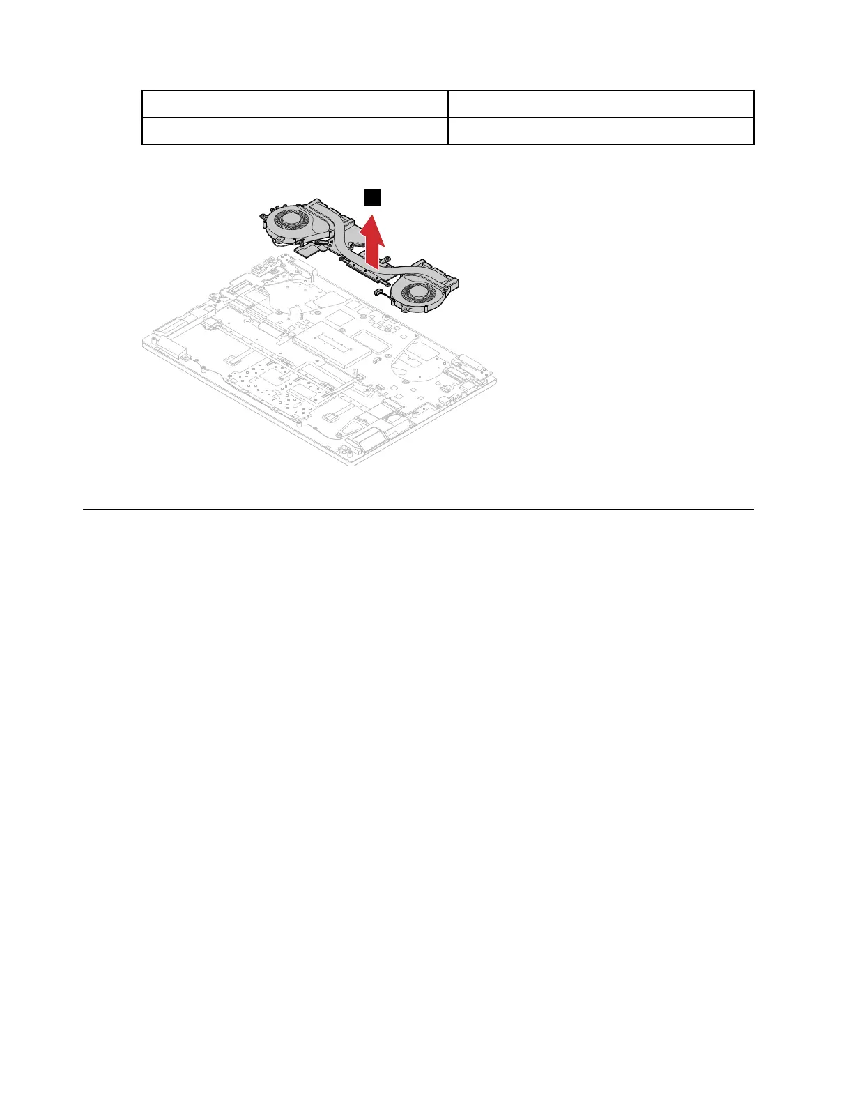
Step 3. Remove the thermal module.
Figure 30. Remove the thermal module
Remove the system board
Make sure the following FRUs (or CRUs) have been removed.
“Remove the lower case” on page 29
“Remove the battery pack” on page 31
“Remove the Wi-Fi card” on page 32
“Remove the M.2 solid-state drive” on page 35
“Remove the memory module” on page 37
“Remove the thermal module” on page 42
Step 1. Detach the I/O board connector, keyboard cable connector, fingerprint cable connector, touchpad
cable connector, speakers cable connector, dc-in cable connector and EDP cable connector from
the system board.
Note: The fingerprint cable is available on selected models.
44
Hardware Maintenance Manual