Front I/O assembly
Use the section to understand the cable routing for front I/O assemblies.
Notes:
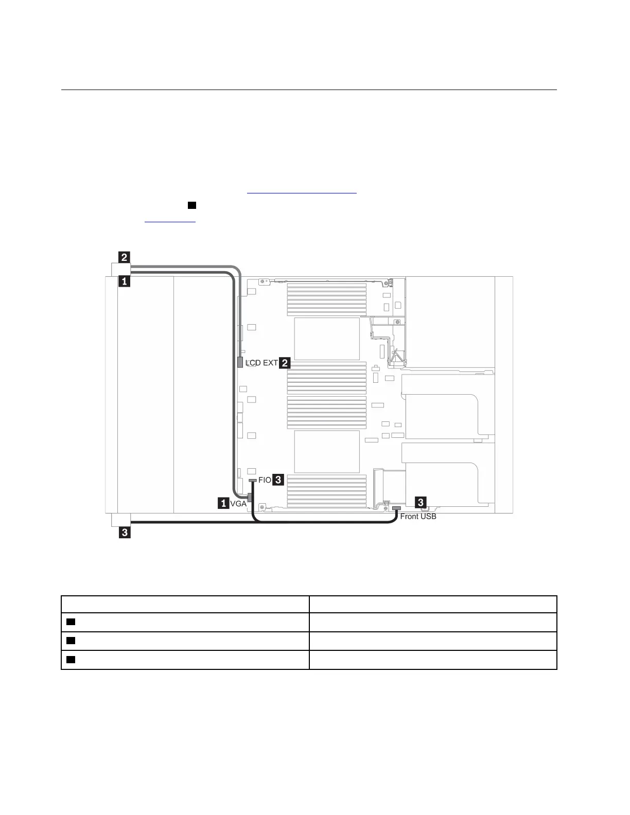
• The illustration shows the cabling scenario for server models with twelve 3.5-inch front drive bays.
Location of each connector on the front of the server varies by models. For detailed location of front I/O
components for different models, see
“Front view” on page 17.
• When routing the callout
3 cable, ensure that it is fixed on the upper frame of the cable retainer. For
details, refer to
“” on page .
Figure 12. VGA connector and front I/O assembly cable routing
From To
1 VGA cable on the left rack latch VGA connector on the system board
2 External diagnostics cable on the left rack latch External LCD connector on the system board
3 Front USB and panel cable on the right rack latch Front I/O and front USB connectors on the system board
62 ThinkSystem SR665 Setup Guide

 Loading...


