Figure 3. XClarity Controller network access label on the pull-out information tab
Front view
This section contains information about the controls, LEDs, and connectors on the front of the server.
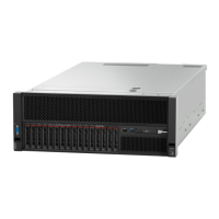
The following illustration shows the controls, LEDs, and connectors on the front of the server.
Figure 4. Front view
Table 2. Components on the server front view
1 VGA connector 7 Network activity LED (green)
2 Drive activity LED (green) 8 Identification button/LED (blue)
3 Drive status LED (yellow) 9 System error LED (yellow)
4 USB 1 (USB 2.0 with Lenovo XClarity Controller
management)
10 Front operator panel with optional pull-out LCD
display
5 USB 2
11 Rack release latches
6 Power button/LED (green)
12 2.5-inch drive bays
12 ThinkSystem SR860 Maintenance Manual

 Loading...


