3
N/A Optical-drive bay
1: Optical/tape
drive
Optical-drive bay
1: Optical/tape
drive
Optical-drive bay
1: Optical/tape
drive
Optical-drive bay
1: Optical/tape
drive
4
Three SATA drives
(Bay 4, 5, 6) and
one SATA/NVMe
drive (Bay 7)
Two SATA drives
(Bay 4, 5)
Four SAS/SATA
drives (Bay 4 to 7)
Eight SAS/SATA
drives (Bay 8 to 15)
Eight SAS/SATA
drives (Bay 4 to 11)
5
Four SATA drives
(Bay 0 to 3)
Four SATA drives
(Bay 0 to 3)
Four SAS/SATA
drives (Bay 0 to 3)
Eight SAS/SATA
drives (Bay 0 to 7)
Four SAS/SATA
drives (Bay 0 to 3)
Note: When ThinkSystem 4350/5350/9350 series RAID adapters are installed, drive number starts from 1
instead of from 0.
Front panel
The front panel of the server provides controls, connectors, and LEDs.
The following illustration shows the control, connectors, and LEDs on the front panel of the server.
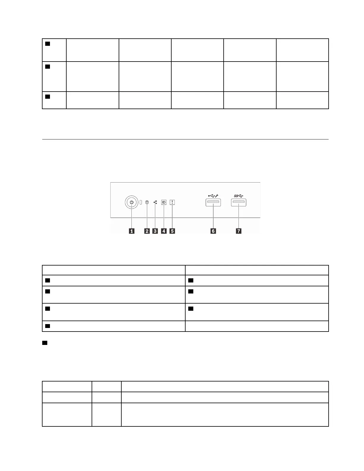
Figure 8. Front panel
Table 4. Components on the front panel
Callout Callout
1 Power button with power status LED (green) 5 System error LED (yellow)
2 Drive activity LED (green)
Note: For onboard SATA indication only
6 XClarity Controller USB 2.0 connector
3 Network activity LED (green)
Note: For onboard LAN indication only
7 USB 3.2 Gen 1 connector
4 System ID button with system ID LED (blue)
1 Power button with power status LED
You can press the power button to turn on the server when you finish setting up the server. You also can hold
the power button for several seconds to turn off the server if you cannot turn off the server from the operating
system. The power status LED helps you determine the current power status.
Status Color
Description
Solid on Green
The server is on and running.
Slow blinking
(about one flash
per second)
Green The server is off and is ready to be powered on (standby state).
Chapter 2. Server components 19

 Loading...


