3. To access the system board, remove the following parts if any:
a. “PCIe card” on page 103
b. “M.2 solid-state drive” on page 109
c. “Memory module” on page 115
d. “Coin-cell battery” on page 131
e. “Power supply assembly” on page 134
f. “Power button” on page 150
g. “Front audio and USB assembly and card reader ” on page 153
h. “Front fan” on page 156
i. “Rear fan” on page 157
j. “Heat-sink-and-fan assembly” on page 159
k. “Microprocessor” on page 173
l. “Wi-Fi units” on page 163
4. Record the cable routing and cable connections and then disconnect all cables from the system board.
See “Parts on the system board” on page 38.
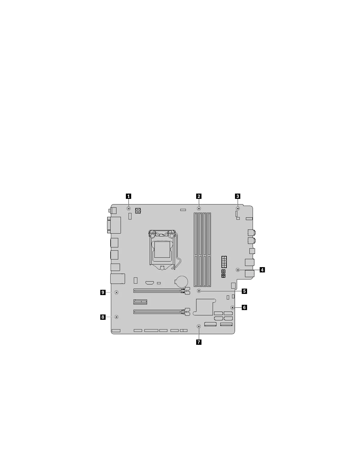
5. Follow the sequence as shown to remove the nine screws that secure the system board.
Figure 154. Removing the nine screws that secure the system board
6. Slide the system board to the front of the computer and then carefully lift the system board out of the
chassis.
7. Remove the microprocessor from the failing system board and install it on the new system board. See
“Microprocessor” on page 173.
176
P330 Hardware Maintenance Manual