Commissioning
Commissioning steps (overview)
Setting of homing
6
97
EDBCSXM064 EN 11.0
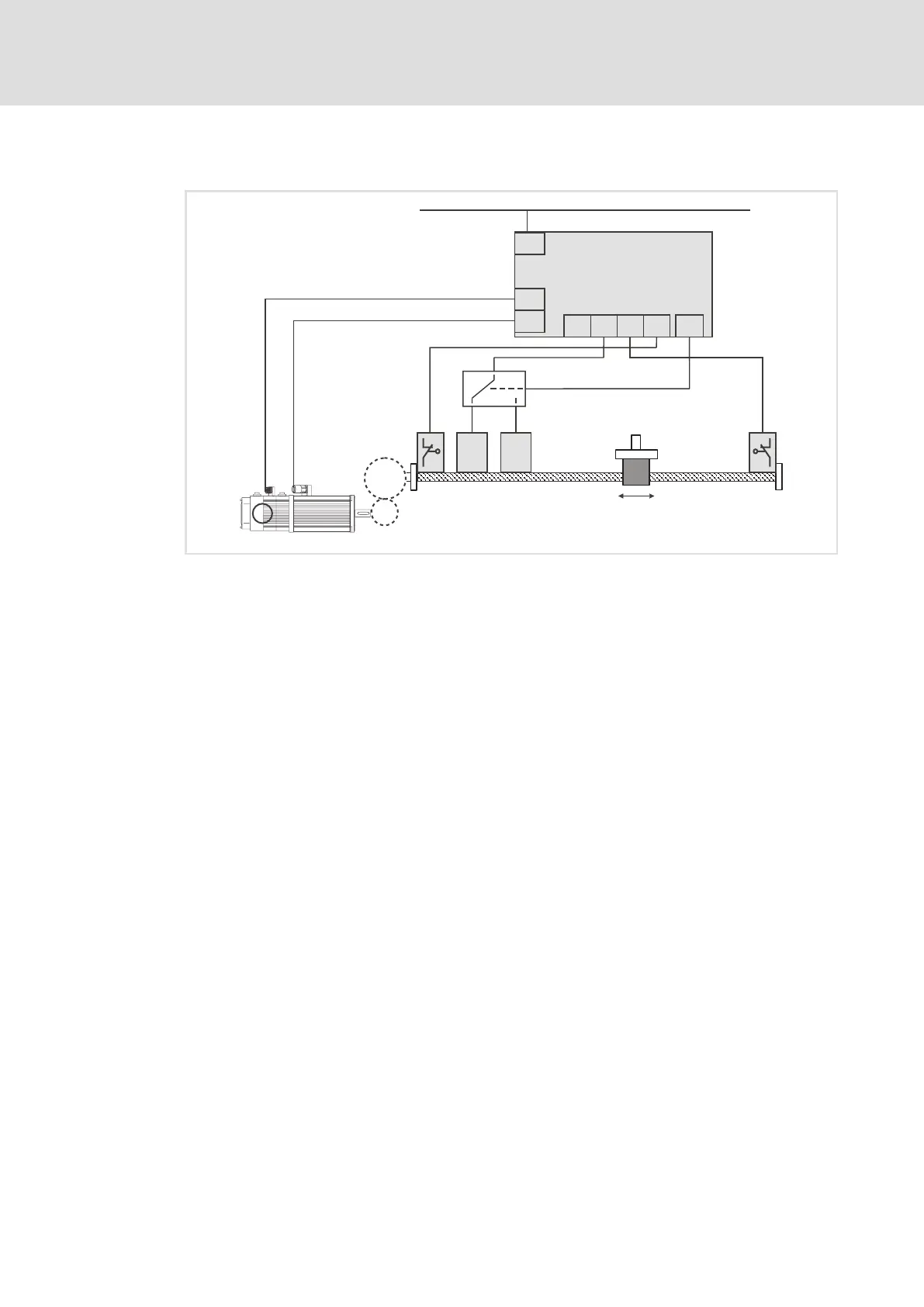
The homing setting described in this chapter requires the following system structure:
Ref
Z2
CAN-AUX
Z1
1
2
3
4
5
7
6
9
DI1
DI2
DI3
DI4
ECSxM...
X6
X24
X7
X14
R
0
TP
DO1
8
0
1
ECSXA500
Fig. 6−2 Basic system structure
ECSxM... axis module with "Motion" application software
Speed / position feedback
Motor power connection
Change−over between reference switch and touch probe sensor
(only required in the homing modes 6 and 7! 145)
Negative hardware limit switch
Reference switch
Touch probe sensor
Positive hardware limit switch
Gearbox with ratio i = Z2/Z1 (ratio of the number of teeth or circumferences) or i = n1/n2
(ratio of speeds)
Servo motor