


D
Dylan CrawfordAug 27, 2025
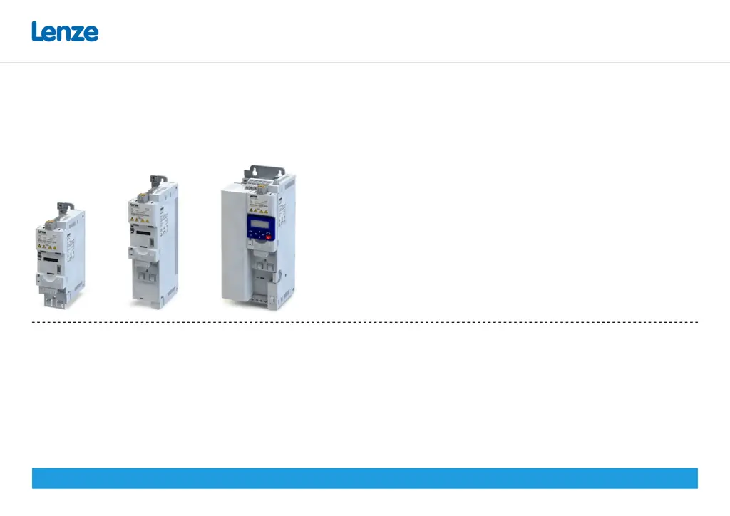
What to do if my Lenze i550 shows motor overtemperature?
- JJay SalasAug 27, 2025
If your Lenze Inverter indicates motor overtemperature, you should: * Check drive sizing. * Check motor thermal sensor and wiring (X109/T1 and X109/T2).


